Device and method for positioning moving workpiece

A workpiece and motion technology, applied in the field of positioning devices for workpieces in motion, can solve problems such as weak adaptability and low positioning accuracy, and achieve the effects of high work efficiency, high-precision positioning, and simple structure

Pending Publication Date: 2015-11-25
上海卫岚电子科技股份有限公司
View PDF5 Cites 1 Cited by
  • Summary
  • Abstract
  • Description
  • Claims
  • Application Information

AI Technical Summary

Problems solved by technology

[0002] At present, in the known production lines or inspection and testing lines, the workpieces with uncertain specific positions at the entrance are mechanically limited and positioned through narrow grooves to control the position of the workpieces at the exit end in the direction of the normal direction of motion, that is, the direction perpendicular to the direction of motion. , this positioning method has low positioning accuracy and weak adaptability

Method used


Image

  • Device and method for positioning moving workpiece
  • Device and method for positioning moving workpiece
  • Device and method for positioning moving workpiece

Examples


example 1

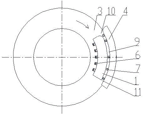
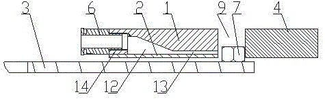
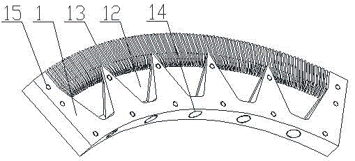
[0024] See figure 1 , figure 2 and image 3 as shown, figure 1 , figure 2 and image 3 Shown is the workpiece positioning method in motion of the present invention, including air knife main body 1, air knife cover 2, moving base plate 3, positioning block 4, pneumatic joint 6; air knife main body 1 and positioning block 4 are fixed, and moving base plate 3 is It is circular and rotates around its vertical center axis. An arc-shaped workpiece channel 9 is formed between the air knife main body 1 and the positioning block 4. The width of the workpiece channel 9 is greater than the maximum dimension of the workpiece 7 in the vertical projection direction. The workpiece channel 9 is two The ends are the workpiece channel inlet 11 and the workpiece channel outlet 12 respectively. There are air cavity 12, air hole array 13, air joint screw hole 14 and air knife cover screw hole 15 on the air knife main body 1, and the air knife cover 2 passes through the air knife cover screw ...

example 2

[0028] Instance 2 please refer to Figure 4 and Figure 5 As shown, the second example is a variant of the first example, which is basically the same as Figure 1~Figure 3 The specific embodiments shown are the same, and the same components use the same reference numerals. Compared with Example 1, the second example adds a pneumatic joint 8 and a positioning block bottom plate 5, and the positioning block bottom plate 5 is fixed on the positioning block 4. The pneumatic joint 8 is installed on the positioning block 4; the structure of the positioning block 4 is similar to that of the air knife main body 1, and also has an air hole array and an air cavity,

[0029] When working, the pneumatic joint 8 is connected to the external vacuum pump so that the air can be sucked away from the workpiece channel 9 to form a negative pressure on the side of the workpiece channel 9 close to the positioning block 4. This negative pressure acts alone or with the airflow from the air knife ma...

example 3

[0031] For example three, please refer to Figure 6 As shown, the third example is a variant of the first example, which is basically the same as Figure 1~Figure 3 The specific embodiments shown are the same, and the same components use the same reference numerals. Compared with Example 1, Example 3 has five air cavities 12 in the air knife main body 1 of Example 1, and there are 5 air connector screw holes 14 correspondingly. , 5 pneumatic joints 6 are installed, so that each section of the air hole array 13 at different positions of the air knife main body 1 is adjustable to adjust the air pressure independently, and the example three has only one air chamber 12, and the air outlet of the air hole array 13 in the example three The air pressure is not adjustable in sections.


PUM


Abstract

The invention relates to a device for positioning a moving workpiece. The device comprises an air knife, a positioning block and a movable base plate. An approximately-parallel workpiece channel is formed between the air knife and the positioning block, and the width of the workpiece channel is larger than the maximum boundary dimension of the vertical projection of the workpiece. A spilehole array is arranged on the side, facing the workpiece channel, of the air knife, high-pressure air flows out through spileholes, so that air pressure difference is formed between the surface, facing the air knife, of the workpiece and the surface, facing the positioning block, of the workpiece on the workpiece channel, the workpiece is pushed under the air pressure difference to be attached to the positioning block, and the workpiece is placed on the movable base plate, moves horizontally along with the movable base plate to an outlet of the workpiece channel after entering the workpiece channel and is positioned during movement.

Description

technical field [0001] The invention relates to a device and method for locating workpieces in motion, which is mainly suitable for locating discrete workpieces in the workpiece flow one by one during the motion process in a production assembly line or an inspection and test assembly line. Background technique [0002] At present, in the known production lines or inspection and testing lines, the workpieces with uncertain specific positions at the entrance are mechanically limited and positioned through narrow grooves to control the position of the workpieces at the exit end in the direction of the normal direction of motion, that is, the direction perpendicular to the direction of motion. , This positioning method has low positioning accuracy and weak adaptability. Contents of the invention [0003] The purpose of the present invention is to overcome the above-mentioned shortcomings in the prior art, and to provide a device and method for positioning discrete workpieces w...

Claims


Application Information

Patent Timeline
Patent Type & Authority Applications(China)
IPC IPC(8): B65G47/88
Inventor 不公告发明人
Owner 上海卫岚电子科技股份有限公司
Why Eureka
Try Eureka