Sediment disposal system for water inlets of power station

A water inlet and power station technology, applied in hydropower stations, water conservancy projects, hydropower, etc., can solve the problems of small flow capacity of sand-drawing holes, small range of scour funnels, and small flow velocity at the mouth, etc., and achieve a significant effect of sand removal , Convenient construction and low water consumption

Inactive Publication Date: 2015-11-25
超飞凡科技(天津)有限公司
View PDF6 Cites 2 Cited by
  • Summary
  • Abstract
  • Description
  • Claims
  • Application Information

AI Technical Summary

Problems solved by technology

For low-head riverbed hubs, it is difficult to arrange the sand discharge bottom holes at the lower part of the water inlet of the power station. They are arranged on both sides of the water inlet of the power station. The scope of the scour funnel is small, and it is difficult to achieve the ideal sand discharge effect.
In addition, the front edge of the water inlet of this type of power station is generally relatively long, and a single sand discharge hole cannot achieve its purpose at all, and it is difficult to arrange multiple sand discharge holes along the front edge of the water inlet.
The Bapanxia Hydropower Station set up equal-width gaps to discharge sand on the top of the corridor on the bottom plate of the inlet section of the power station. The operation results show that the flow rate at the gate is small, the flow capacity of the sand-drawing hole is small, the sand-drawing range is not large, and it is easy to generate sand in the corridor. clogging

Method used


Image

  • Sediment disposal system for water inlets of power station
  • Sediment disposal system for water inlets of power station
  • Sediment disposal system for water inlets of power station

Examples


Embodiment Construction

[0014] Below in conjunction with embodiment and attached Figure 1-3 The present invention is described further:

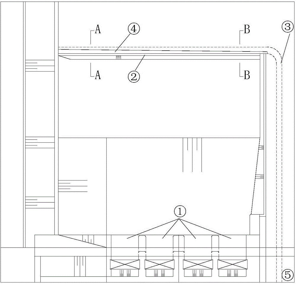
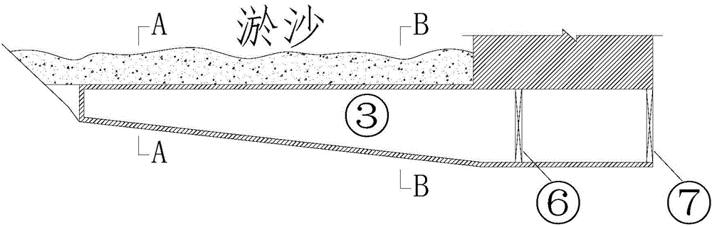
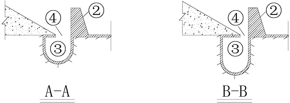
[0015] The sand discharge system of the power station water inlet of the present invention includes a sand retaining ridge 2, a sand delivery corridor 3 and a dam foundation sand discharge hole 5, and the dam foundation sand discharge hole 5 is arranged on the right side of the power station water inlet 1, and the The sand discharge tunnel 5 of the dam foundation is provided with a sand discharge tunnel maintenance door 6 and a sand discharge tunnel working door 7; The sand delivery corridor 3, the sand delivery corridor 3 is connected to the dam foundation sand discharge hole 5, and a horizontal seam sand discharge port 4 is provided on the top of the sand conveyance corridor 3, and the horizontal seam sand discharge port The width of 4 gradually narrows from the upstream, and the cross-section of the sand delivery corridor 3 gradually increases from the upstrea...


PUM


Abstract

The invention relates to a sediment disposal system for water inlets of a power station, belonging to the field of hydraulic engineering. The IPC (International Patent Classification) numbers of the sediment disposal system are E02B9 / 00, E02B9 / 04 and E02B1 / 00. The sediment disposal system is characterized in that a sediment barrier is laid at the front edge of the water inlet of the power station along the whole line; a sediment transporting gallery is laid in front of the sediment barrier along the whole line and is connected with a sediment disposal hole of a dam foundation; a horizontal seam sediment disposal opening is formed in the top of the sediment transporting gallery; the width of the horizontal seam sediment disposal opening is gradually reduced from the upstream; a cross section of the sediment transporting gallery is gradually increased from the upstream; the sediment barrier is matched with the width-variable seam type sediment transporting gallery for use to play a role of a sediment trapping trough; a strip-shaped flushing funnel can be formed in front of the sediment barrier, so that the sediment disposal effect of cleaning the sediment in front of the water inlet of the power station is really realized.

Description

Technical field: [0001] The invention relates to a technique for removing coarse-grained sediment from a water inlet of a hydropower station, in particular to a technique for discharging sand using variable-width and narrow-slit sand-discharging corridors of unequal width, which belongs to the field of water conservancy engineering. The IPC international patent classification number is E02B9 / 00, E02B9 / 04, E02B1 / 00. Background technique: [0002] On sandy rivers, the destructive effect of sediment wear on turbines is very serious. For high water head projects, setting up sand discharge bottom holes or flood discharge and sand discharge holes is an effective measure to reduce the passage of coarse sand. The sand discharge bottom hole is generally arranged at the lower part of the water inlet of the power station, and the flood discharge is used to form a scour funnel in front of the water inlet of the power station to reduce the flow of coarse sand. For low-head riverbed hu...

Claims


Application Information

Patent Timeline
Patent Type & Authority Applications(China)
IPC IPC(8): E02B9/00E02B9/04
CPCY02E10/20
Inventor 傅酉付玉生
Owner 超飞凡科技(天津)有限公司
Why Eureka
Try Eureka