
A sand discharge method for the water inlet of a low-head riverbed-type pivotal power station

A water inlet, low head technology, applied in the direction of hydropower station, hydropower, traditional hydropower energy, etc., can solve the problems of small flow capacity of lasha hole, small range of scouring funnel, small flow rate at the entrance, etc. The sand effect is obvious, the construction is convenient, and the water consumption is small.

Inactive Publication Date: 2015-12-02
YELLOW RIVER INST OF HYDRAULIC RES YELLOW RIVER CONSERVANCY COMMISSION
View PDF8 Cites 0 Cited by
  • Summary
  • Abstract
  • Description
  • Claims
  • Application Information

AI Technical Summary

Problems solved by technology

For low-head riverbed hubs, it is difficult to arrange the sand discharge bottom holes at the lower part of the water inlet of the power station. They are arranged on both sides of the water inlet of the power station. The scope of the scour funnel is small, and it is difficult to achieve the ideal sand discharge effect.
In addition, the front edge of the water inlet of this type of power station is generally relatively long, and a single sand discharge hole cannot achieve its purpose at all, and it is difficult to arrange multiple sand discharge holes along the front edge of the water inlet.
The Bapanxia Hydropower Station set up equal-width gaps to discharge sand on the top of the corridor on the bottom plate of the inlet section of the power station. The operation results show that the flow rate at the gate is small, the flow capacity of the sand-drawing hole is small, the sand-drawing range is not large, and it is easy to generate sand in the corridor. clogging

Method used


Image

  • A sand discharge method for the water inlet of a low-head riverbed-type pivotal power station
  • A sand discharge method for the water inlet of a low-head riverbed-type pivotal power station
  • A sand discharge method for the water inlet of a low-head riverbed-type pivotal power station

Examples


Embodiment Construction

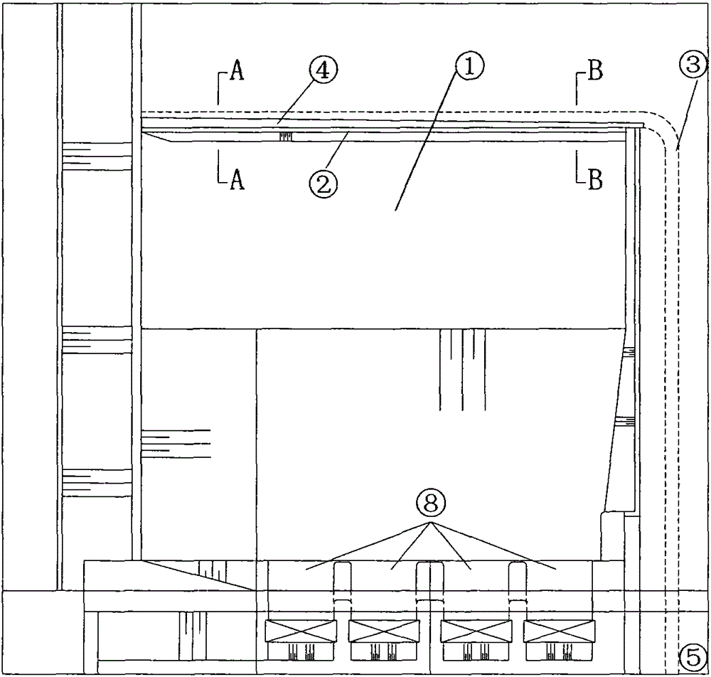
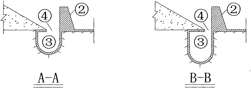
[0017] The following examples and attachments are combined Figure 1-3 To further explain the present invention:

[0018] The method for discharging sand at the water inlet of a low-head riverbed junction power station of the present invention includes building layout and operation modes:

[0019] (1) Building layout: a dam foundation sand discharge tunnel 5 is set on the right side of the power station water inlet 1, and the dam foundation sand discharge tunnel 5 is provided with a sand discharge tunnel inspection door 6 and a sand discharge tunnel working door 7. A sand barrier 2 is arranged along the front edge of the water inlet 1 of the power station, and a sand conveyance corridor 3 is arranged in front of the sand barrier 2. The sand conveyance corridor 3 is connected to the dam foundation sand discharge tunnel 5. A horizontal seam sand discharge port 4 is provided on the top of the sand conveyance corridor 3, and the width of the horizontal seam sand discharge port 4 gradu...


PUM


Abstract

The invention relates to a sediment releasing method for a water intake of a low-head river channel pivotal power station and belongs to the field of water conservancy projects, under the IPC numbers of E02B9 / 00, E02B9 / 04 and E02B1 / 00. According to the method, a sediment trap is arranged along the whole front edge of the power station water intake, a gallery for sediment transport is arranged in front of the sediment trap and connected with a dam base sediment tunnel, the top of the gallery for sediment transport is provided with a horizontal joint sediment outlet, the width of the horizontal joint sediment outlet gradually increases from the upstream, the cross section of the gallery for sediment transport gradually increases from the upstream. The sediment trap is used with the variable width joint type gallery for sediment transport so as to achieve the function of an intercepting channel, an elongated scour funnel can be formed in front of the sediment trap, and the sediment releasing effect that sediment is released in front of the power station water intake is truly achieved.

Description

Technical field: [0001] The invention relates to a technology for removing coarse particles of sand from a water inlet of a hydropower station, and in particular to a technology for removing sand by adopting a widening and narrow-slit sand discharge corridor of unequal width, which belongs to the field of water conservancy engineering. The IPC international patent classification number is E02B9 / 00, E02B9 / 04, E02B1 / 00. Background technique: [0002] On sandy rivers, the damaging effect of sand abrasion on hydraulic turbines is very serious. For high-head hubs, setting up bottom holes or flood discharge tunnels is an effective measure to reduce the amount of coarse sand passing through. The bottom hole of sand discharge is generally arranged at the lower part of the water inlet of the power station, and the flood discharge is used to form a scour funnel in front of the water inlet of the power station to reduce the coarse sand passing through the machine. For a low-head riverbed...

Claims


Application Information

Patent Timeline
Patent Type & Authority Patents(China)
IPC IPC(8): E02B8/02E02B9/00
CPCY02E10/22Y02E10/20
Inventor 武彩萍李远发赵连军吴国英陈俊杰刘刚森江恩慧宋莉萱朱超任艳粉王嘉仪罗立群史海英耿莉樊文玲张林波朱智伟
Owner YELLOW RIVER INST OF HYDRAULIC RES YELLOW RIVER CONSERVANCY COMMISSION
Learn More