Semi-automatic water pump performance test platform

A water pump performance and test platform technology, applied in pump control, non-variable pumps, machines/engines, etc., can solve problems such as multiple equipment specifications, electrical failures, height and dimension changes, etc., to avoid electrical failures and solve vibration problems , the effect of high degree of automation

Active Publication Date: 2015-11-25
大连桐程自动化设备有限公司
View PDF6 Cites 3 Cited by
  • Summary
  • Abstract
  • Description
  • Claims
  • Application Information

AI Technical Summary

Problems solved by technology

Among them, the scheme of the first lifting platform is as follows: Image 6 As shown: it is supported by four lead screws 22, and the motor 9 drives the lead screws 22 to rotate and lift synchronously. Since there is a certain gap between the lead screws 22 and the screw nut, when the test load reaches about 70% (55kw) of its power, the motor 9 The platform 5 (fixed together) with the water pump has just produced violent vibration (the noise reaches more than 85 decibels), and the violent vibration will also cause: 1, the change of the height of the platform 5; 2, the motor 9 and the water pump 6 axis 3. Vibration will cause the gap between the lead screw 22 and the screw nut to become larger and larger; 4. Since the center of the sprocket 20 is perpendicular to the horizontal plane, the chain 21 is driven in an unreasonable state, and the chain 21 is very easy to get stuck and fall off. It cannot work normally; 5. Electrical failure caused by accidental water leakage
In summary, the platform 5 cannot normally perform the full load test of the water pump 6
The second is to use matching fixed pads. Although the problem of vibration is avoided, it has problems such as large size changes, many equipment specifications, and high labor intensity of workers, which cannot meet the needs of modern production.

Method used


Image

  • Semi-automatic water pump performance test platform
  • Semi-automatic water pump performance test platform
  • Semi-automatic water pump performance test platform

Examples


Embodiment Construction

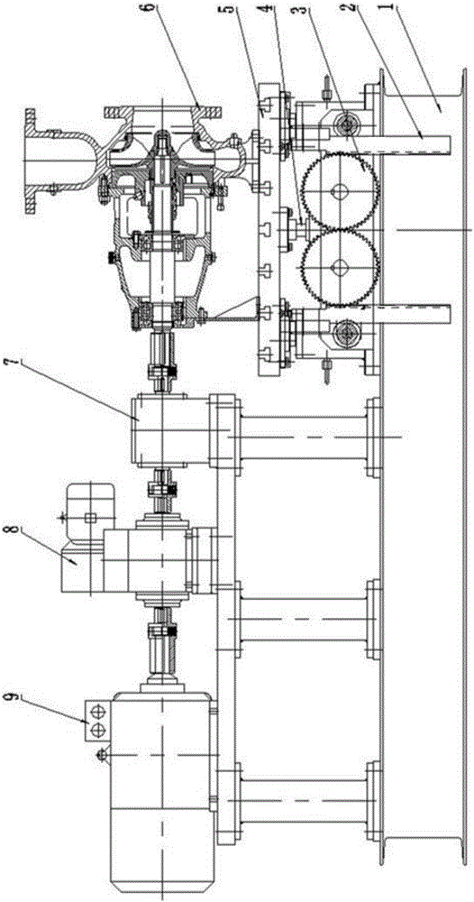
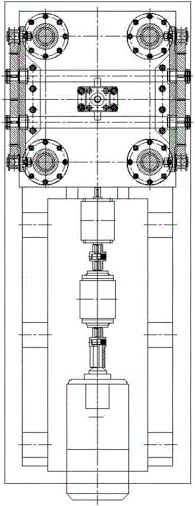
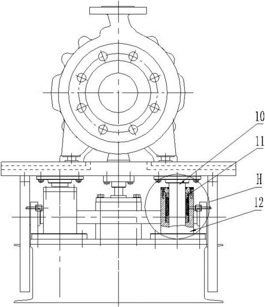
[0021] Such as Figure 1-Figure 5 As shown, the semi-automatic water pump performance test platform includes a base 1, a platform 5, a water pump 6, and a motor 9. The water pump 6 is installed on the platform 5, and the motor 9 is installed on the base 1. It also includes a rack 2, a gear 3, and an oil cylinder 4. Torque meter 8, guide post 10, thin-walled sleeve 11, support sleeve 12 and pressurized oil cylinder, four racks 2 are fixed around the bottom of platform 5 and are located on both sides of base 1 in pairs, between the racks 2 on each side There are two gears 3 meshed between them. The gears 3 are used to prevent the platform 5 from tilting, so that the racks 2 can rise and fall at the same time. A gear shaft is installed between the opposite gears 3 on both sides. Adjusting bolts are provided on each rack 2. First adjust the positions of the two gears 3, then adjust the positions of the two racks 2, and tighten the adjusting bolts to ensure the meshing gap between ...


PUM


Abstract

The invention discloses a semi-automatic water pump performance test platform. The platform lifting and falling are completed by an oil cylinder, and meanwhile, a platform is positioned by four guide pillars fixed under the platform; gear and rack structures performing opposite movement are adopted, so that the four guide pillars are driven to move simultaneously, and the platform lifts or falls horizontally and is not inclined; with the adoption of thin wall sleeve structures, the guide pillars can be tightly clamped at any height, the platform and a base are connected without gaps, and the problem of vibration of the platform is completely solved; with the adoption of the pressurized oil cylinder, the guide pillars are tightly clamped by the thin wall sleeves when the system is under low working pressure; the lifting displacement is digitally displayed, the automation degree and the accuracy are high, observation is facilitated, and the operation is simple and convenient; hydraulic lifting is adopted to replace original electric screw lifting, an electric appliance fault caused by accidental water leakage is avoided, the existing defects of the water pump test platform are overcome, and the test requirements of various types of centrifugal water pumps are really met.

Description

technical field [0001] The invention relates to the technical field of performance testing of water pumps, in particular to a semi-automatic water pump performance testing platform. Background technique [0002] According to the domestic water pump industry association, the performance (pressure and flow) testing technology and equipment of centrifugal water pumps before leaving the factory are very backward. Since the centrifugal water pump has many specifications, the size and weight change greatly (motor power 18.5-160kw), it brings great difficulties to the test work. When the motor and the water pump rotate at high speed synchronously, vibration is easily generated. Tested on the existing lifting platform, its maximum power cannot exceed 70% (55kw), so the full load test cannot be carried out, and the actual parameters of the water pump cannot be truly reflected. [0003] At present, there are two main types of technical equipment used for water pump performance testin...

Claims


Application Information

Patent Timeline
Patent Type & Authority Applications(China)
IPC IPC(8): F04D15/00
Inventor 李玉贵
Owner 大连桐程自动化设备有限公司
Why Eureka
Try Eureka