shock absorber

A technology of shock absorbers and raised parts is applied in the field of vibration reduction, which can solve the problems of easy shaking, limited contact area, and limited shear force, so as to achieve the ability to improve the high-speed rotation speed of the fan blade and reduce the detachment. Possibility, effect of increasing contact area

Active Publication Date: 2018-02-09
GREE ELECTRIC APPLIANCES INC
View PDF8 Cites 0 Cited by
  • Summary
  • Abstract
  • Description
  • Claims
  • Application Information

AI Technical Summary

Problems solved by technology

However, with the increase of the axial thickness, the overall size of the insert also increases, and the use in small space is limited.
Generally, small and thin inserts often design the radial rubber layer thickness to be thinner (generally, the radial thickness is 4-5mm), but the vibration isolation requirements cannot be met.
To meet the vibration isolation requirements, the thickness of the radial rubber layer must be increased, and the structural reliability cannot be satisfied.
The contact area between the rubber layer of the existing insert and the inner and outer jackets is limited, the shear force that can withstand is limited, the reliability cannot be satisfied, and it is easy to shake under the action of torque

Method used


Image

  • shock absorber
  • shock absorber
  • shock absorber

Examples


Embodiment 1

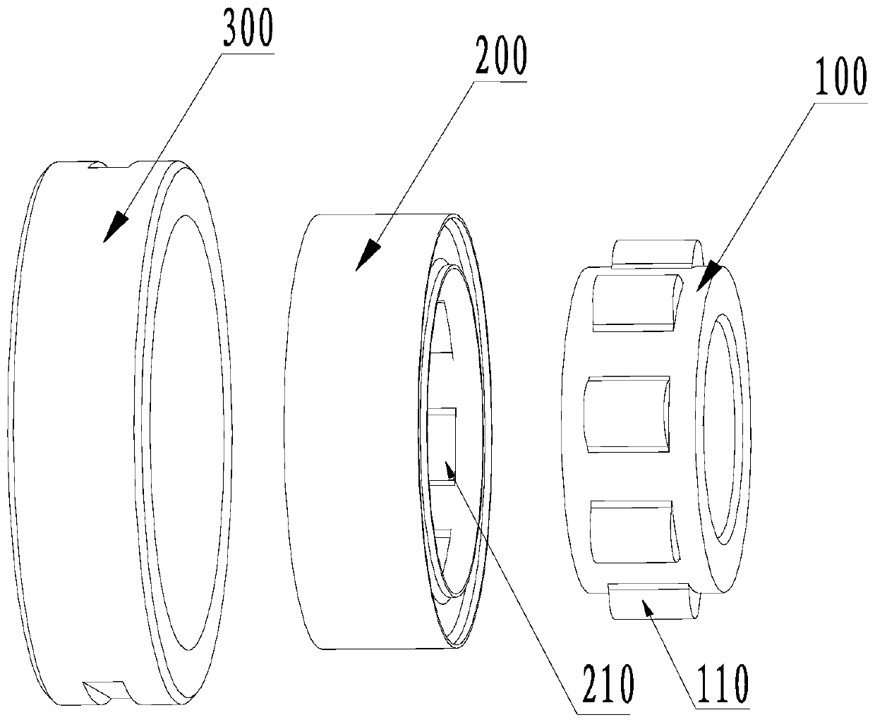
[0054] Such as figure 1 with figure 2 As shown, as an implementation manner, the outer surface of the inner sleeve 100 is uniformly provided with a plurality of first protrusions 110, and the inner surface of the intermediate layer 200 is provided with a plurality of first protrusions 110 one by one. Corresponding to the second groove 210, the first protrusion 110 is embedded in the second groove 210. In this way, the contact area between the inner sleeve 100 and the intermediate layer 200 is increased, and when the shock absorber is subjected to torque during operation, the possibility of the inner sleeve 100 and the intermediate layer 200 being separated is reduced, and the shock absorber is increased The ability of the wind blade to rotate at a high speed improves the reliability of the shock absorber.

[0055] Of course, the first protrusion 110 provided on the outer surface of the inner sleeve 100 can also be a ring-shaped boss arranged concentrically on the outer periphery...

Embodiment 2

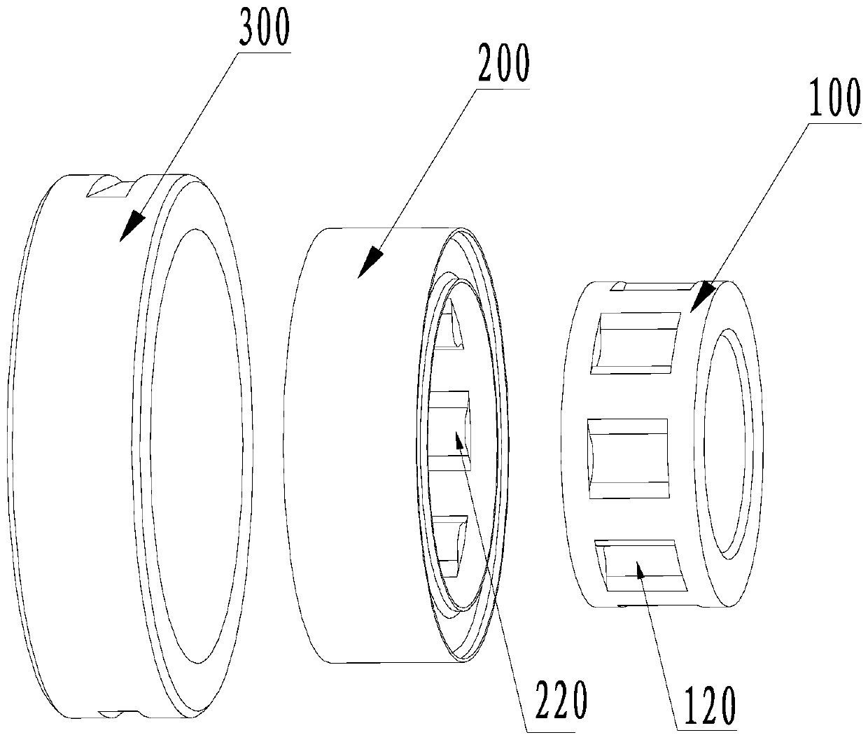
[0058] Such as image 3 with Figure 4 As shown, the outer surface of the inner sleeve 100 is uniformly provided with a plurality of first grooves 120, and the inner surface of the intermediate layer 200 is provided with a plurality of second protrusions 220 corresponding to the first grooves 120 one by one. The second protrusion 220 is embedded in the first groove 120. In this way, the contact area between the inner sleeve 100 and the intermediate layer 200 is increased, and when the shock absorber is subjected to torque during operation, the possibility of the inner sleeve 100 and the intermediate layer 200 being separated is reduced, and the shock absorber is increased The ability of the wind blade to rotate at a high speed improves the reliability of the shock absorber.

[0059] Of course, the first groove 120 provided on the outer surface of the inner sleeve 100 can also be a ring-shaped groove concentrically provided on the outer periphery of the inner sleeve 100. At this t...

Embodiment 3

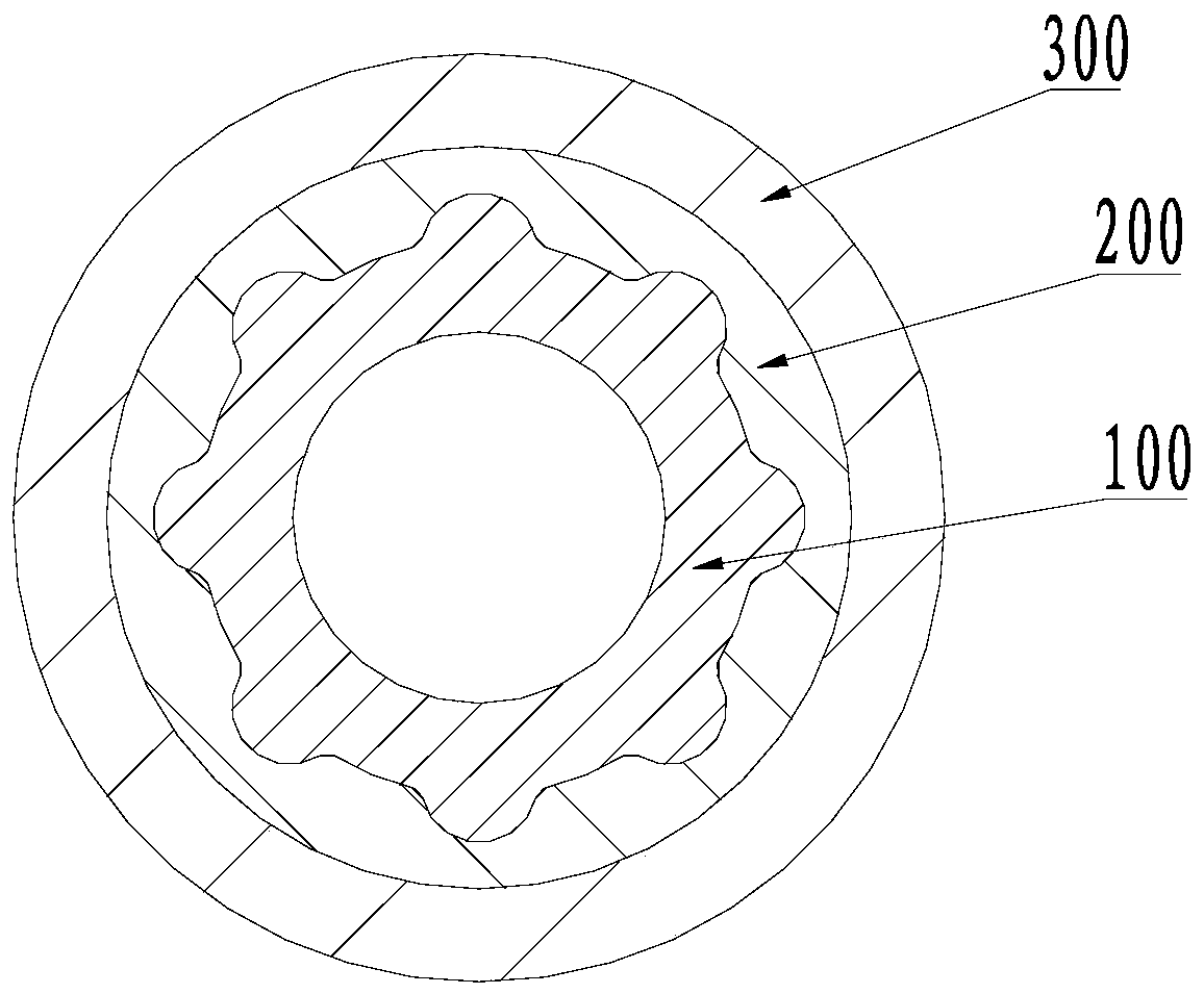
[0062] Such as Figure 5 with Image 6 As shown, as a further improvement, the outer surface of the inner sleeve 100 is uniformly provided with a plurality of first protrusions 110, and the inner surface of the intermediate layer 200 is provided with a plurality of first protrusions 110 corresponding to each other. In the second groove 210, the first protrusion 110 is embedded in the second groove 210. In this way, the contact area between the inner sleeve 100 and the intermediate layer 200 is increased, and when the shock absorber is subjected to torque during operation, the possibility of the inner sleeve 100 and the intermediate layer 200 being separated is reduced, and the shock absorber is increased The ability of the wind blade to rotate at a high speed improves the reliability of the shock absorber.

[0063] Of course, the first protrusion 110 provided on the outer surface of the inner sleeve 100 can also be a ring-shaped boss arranged concentrically on the outer periphery...


PUM


Abstract

The invention provides a shock absorber. The shock absorber comprises an inner sleeve, a middle layer and an outer sleeve. First protrusion portions or first grooves are arranged on or formed in the outer side face of the inner sleeve. Second grooves matched with the first protrusion portions or second protrusion portions matched with the first grooves are formed in or arranged on the inner side face of the middle layer. The inner sleeve, the middle layer and the outer sleeve are arranged concentrically from inside to outside in sequence. According to the shock absorber, the protrusion portions or the grooves are arranged on or formed in the outer side face of the inner sleeve, and the grooves or and the protrusions are formed in or arranged on the inner layer face of the middle layer correspondingly, so that the contact area between the inner sleeve and the middle layer is increased, and the probability of separation of the inner sleeve and the middle layer when the shock absorber is subjected to turning moment during running is reduced; the capacity of the shock absorber to bear a high rotation speed o fan blades is improved, the stability of the shock absorber under the action of twisting moment, turning moment and axial force is improved, and therefore the reliability of the shock absorber is improved.

Description

Technical field [0001] The present invention relates to the technical field of vibration reduction, in particular to a shock absorber. Background technique [0002] Metal and rubber composite shock absorbers (inserts) are a kind of rubber shock absorbers. This type of parts combines the high damping characteristics of rubber materials and the high stiffness characteristics of metal materials to solve the characteristics that ordinary materials cannot meet. Fan blade inserts used in air conditioners have gradually evolved from single metal inserts to metal and rubber composite vibration isolation inserts. This type of insert takes advantage of the high damping characteristics of rubber materials and the high stiffness characteristics of metal materials. Used to eliminate the problem of motor commutation noise. [0003] In order to solve the problem of the reliability of the insert structure, it is usually to increase the axial thickness of the insert. After the thickness is increas...

Claims


Application Information

Patent Timeline
Patent Type & Authority Patents(China)
IPC IPC(8): F16F7/00
CPCF16F7/00
Inventor 夏增强高旭高智强林麟程诗刘江驰
Owner GREE ELECTRIC APPLIANCES INC
Why Eureka
Try Eureka