
Tensioning device for spoke out-of-roundness positioning check tool

A technology of out-of-roundness and inspection tools, which is applied in the direction of mechanical counter/curvature measurement, etc., can solve the problems of radial deviation of spokes and reduce the detection accuracy of spoke out-of-roundness, so as to achieve uniform extrusion deformation and prevent radial deviation Move, prevent the effect of local excessive force

Inactive Publication Date: 2015-11-25
CHONGQING DINGHAN MACHINERY
View PDF0 Cites 1 Cited by
  • Summary
  • Abstract
  • Description
  • Claims
  • Application Information

AI Technical Summary

Problems solved by technology

However, the existing positioning and inspection tools can only locate it, and there will be a gap between the middle hole of the spoke and the mandrel, which will easily cause a slight radial deviation of the spoke during the rotation process, thereby reducing the detection of the out-of-roundness of the spoke the accuracy of

Method used


Image

  • Tensioning device for spoke out-of-roundness positioning check tool
  • Tensioning device for spoke out-of-roundness positioning check tool
  • Tensioning device for spoke out-of-roundness positioning check tool

Examples


Embodiment 1

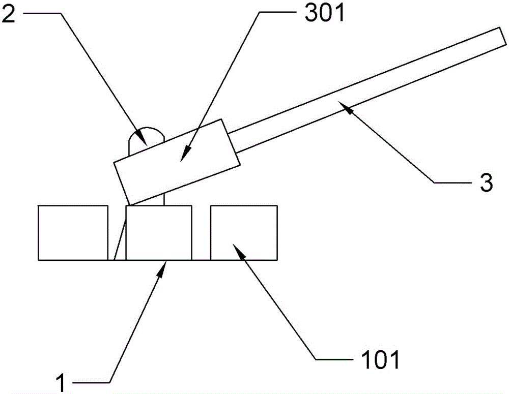
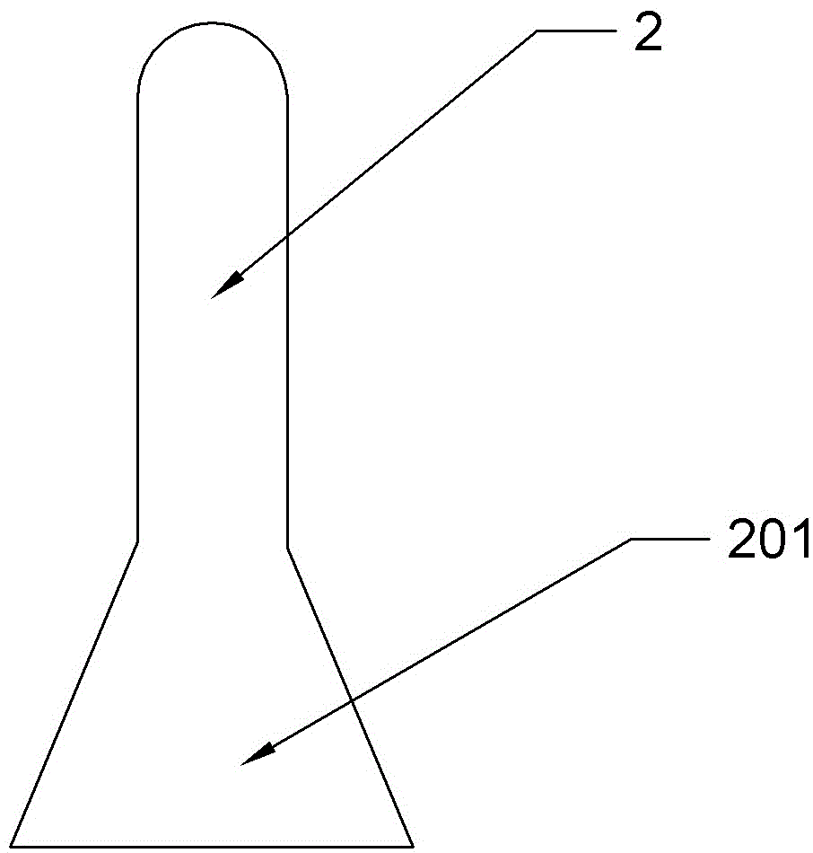
[0021] Example 1, such as figure 1 and figure 2 As shown, the tensioning device used for the spoke out-of-roundness positioning fixture includes a mandrel 1, a protruding rod 2 and a movable rod 3, wherein the protruding rod 2 is located at the center of the mandrel 1, and the movable rod 3 is connected to the top end of the protruding rod 2 . The mandrel 1 is a hollow ring, and there is an expansion groove 101 on the mandrel 1, and the bottom of the mandrel 1 is fixedly connected with the mounting seat of the positioning gauge, which is used to make the extrusion deformation between the mandrel 1 and the spokes more evenly. The protruding rod 2 is used to expand the mandrel 1, and the lower end surface of the protruding rod 2 is provided with a protruding block 201. The protruding block 201 is a positive trapezoid with a narrow top and a wide bottom. The variation of the cross-sectional area of ​​the block 201 is such that the mandrel 1 is pressed outwards. The protrudin...

Embodiment 2

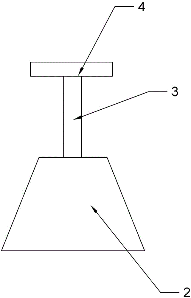
[0022] Example 2, such as image 3 As shown, the difference with Embodiment 1 is that the protruding rod 2 is a positive trapezoid as a whole, the movable rod 3 is located directly above the protruding rod 2, and a handle 4 is arranged on the movable rod 3, and the handle 4 is fixedly connected with the movable rod 3, and the handle 4 is covered with rubber sleeve above. By holding the handle 4 upwards, the protruding rod 2 is lifted up, so that the wide part below the protruding rod 2 presses the mandrel 1 outward.

Embodiment 3

[0023] Example 3, such as Figure 4 As shown, the difference from Embodiment 2 is that the protruding rod 2 is an inverted trapezoid with a wide top and a narrow bottom. By pressing down on the handle 4, the whole protruding rod 2 can be pressed down, so that the upper wide part of the protruding rod 2 presses the mandrel 1 outward.


PUM


Abstract

The invention belongs to the stamping detection field and relates to a spoke out-of-roundness positioning check tool, in particular, a tensioning device for the spoke out-of-roundness positioning check tool. The tensioning device comprises a core shaft and a protruding rod for distending the core shaft; the protruding rod is located in the core shaft; the core shaft is a hollow ring; a tensioning groove is formed in the core shaft along the axial direction of the core shaft; the protruding rod is provided with a protruding block; and the protruding rod is provided with a mobile rod which is used for making the protruding rod move up and down. According to the tensioning device of the invention, the core shaft which can be split into a plurality of core shafts, the protruding rod used for distending the core shaft, and the mobile rod are adopted, and therefore, no gap exists between the central hole of a spoke and the core shaft, and therefore, radial deviation of the spoke in a rotation process can be avoided, and the accuracy of the out-of-roundness detection of the spoke can be ensured.

Description

technical field [0001] The invention relates to the field of stamping testing, in particular to a tensioning device used for a wheel spoke out-of-roundness positioning and checking tool. Background technique [0002] The wheel spoke is a device to protect the rim and spokes of the vehicle wheel. Its structure is generally a pair of circular cover plates. The diameter of the cover plate is similar to the diameter of the wheel rim. The center of the cover plate has a hole larger than the rotation axis of the wheel. There are holes near the edge of the cover plate, and the edge of the cover plate is provided with an annular wheel plate, and the curved surface of the wheel plate can fit closely with the curved surface of the wheel rim. With the rapid development of the automobile industry, more and more people use automobiles as a means of transportation, and the product quality of the spokes has also attracted much attention. Among them, the out-of-roundness of the spokes is a...

Claims


Application Information

Patent Timeline
Patent Type & Authority Applications(China)
IPC IPC(8): G01B5/20
Inventor 刘文
Owner CHONGQING DINGHAN MACHINERY
Learn More