Device and method for detecting signal intensity of frequency-shift excitation raman spectrum based on tunable laser

A technology of signal intensity detection and Raman spectroscopy, applied in the field of signal intensity detection of Raman spectroscopy, can solve the problems of complex structure of frequency-shift excitation device, inability to detect broad-spectrum substances, and poor real-time performance, so as to improve system integration and stability. The effect of reducing system complexity and ensuring the accuracy of measurement

Inactive Publication Date: 2015-11-25
HARBIN INST OF TECH
View PDF8 Cites 13 Cited by
  • Summary
  • Abstract
  • Description
  • Claims
  • Application Information

AI Technical Summary

Problems solved by technology

[0005] The present invention aims to solve the problems of complex structure of the frequency-shift excitation device, poor real-time performance and inability to detect broad-spectrum substances. The method of reversing the original Raman spectrum s

Method used


Image

  • Device and method for detecting signal intensity of frequency-shift excitation raman spectrum based on tunable laser
  • Device and method for detecting signal intensity of frequency-shift excitation raman spectrum based on tunable laser
  • Device and method for detecting signal intensity of frequency-shift excitation raman spectrum based on tunable laser

Examples


Example Embodiment

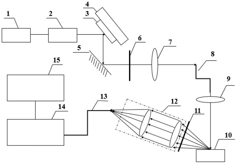
[0031] Embodiment 1: Combining figure 1 This embodiment will be specifically described. The signal intensity detection device based on frequency-shifted excitation Raman spectroscopy of tunable lasers described in this embodiment includes a current driver 1 , a semiconductor laser 2 , a grating 3 , a grating controller 4 , and a mirror. 5. Bandpass filter 6, first convex lens 7, excitation fiber 8, second convex lens 9, sample container 10, high-pass filter 11, coupling lens group 12, collecting fiber 13, spectrometer 14 and spectrum analysis module 15;

[0032] The control signal output end of the current driver 1 is connected to the control signal input end of the semiconductor laser 2. The collimated beam emitted by the semiconductor laser 2 is incident on the grating 3, and the grating 3 is fixed on the grating controller 4. The zeroth order diffracted by the grating 3 The light beam is incident on the mirror 5, the light beam reflected by the mirror 5 is incident on the b...

Example Embodiment

[0034] Embodiment 2: This embodiment further describes the signal intensity detection device based on frequency-shift excitation Raman spectroscopy of tunable laser described in Embodiment 1. In this embodiment, after diffraction by the grating 3, the The optical power of the zeroth-order beam is greater than 100mW, the line width is less than 0.5nm, and the wavelength tuning range is greater than 10nm.

[0035] In the prior art, the wavelength change achieved by current adjustment can usually only reach 0.5 nm, while the wavelength tuning range of this embodiment is greater than 10 nm, which can realize the detection of broad-spectrum substances.

Example Embodiment

[0036] Embodiment 3: This embodiment further describes the signal intensity detection device based on frequency-shifted excitation Raman spectroscopy of tunable laser described in Embodiment 1. In this embodiment, the first convex lens 7 and the excitation The distance range of fiber 8 is (f 1 -5mm)~(f 1 +5mm), f 1 is the focal length of the first convex lens 7 .

[0037] The distance between the first convex lens 7 and the excitation fiber 8 is (f 1 -5mm)~(f 1 The light beam can be coupled into the excitation fiber 8 only when the distance is within the range of +5mm), and almost no light beam is coupled into the fiber when the distance exceeds this range.


PUM

PropertyMeasurementUnit
Optical poweraaaaaaaaaa
Line widthaaaaaaaaaa

Abstract

The invention discloses a device and a method for detecting signal intensity of a frequency-shift excitation raman spectrum based on tunable laser, relates to the technical field of signal intensity detection of raman spectrums, and aims at solving the problems that a frequency-shift excitation device is complicated in structure and poor in real-time performance and cannot detect a wide spectrum material, the process of inverting an original raman spectrum signal according to a differential raman spectrum signal is large in calculated quantity, and an error is introduced. Deflection and pitch attitudes of a grating are controlled by a grating controller; the outgoing wavelength of a semiconductor laser device is changed by changing the deflection angle of the grating; the level of excitation light power is adjusted by controlling the efficiency of coupling a light beam to an excitation fiber; obtained initial differential raman spectrum signals are integrated and normalized to obtain a normalized differential raman spectrum signal; N data points are uniformly extracted and absolute values are taken for summation, so as to obtain a raman spectrum signal intensity value. The device and the method can be used for obtaining the signal intensity of the raman spectrum.

Description

technical field [0001] The invention relates to the technical field of Raman spectrum signal intensity detection. Background technique [0002] Raman spectroscopy is a detection technology with significant advantages such as fast detection speed, no need for pretreatment, no damage to the measured substance, and the ability to completely reflect the internal structure information of the molecule. It is widely used in food safety, chemical analysis and material analysis, etc. field. However, most Raman detection processes will be accompanied by the generation of fluorescent signals. Weak fluorescent signals will seriously interfere with the identification of weak Raman signals, and strong fluorescent signals will even drown out Raman signals. Interference can be very effective in improving detection efficiency. [0003] At present, the effective methods of suppressing fluorescence widely used mainly include fluorescence quenching method, time-resolved method, numerical proc...

Claims


Application Information

Patent Timeline
IPC IPC(8): G01N21/65
Inventor 赵晓荣娄秀涛哈斯乌力吉巴德欣吕志伟
Owner HARBIN INST OF TECH
Why Eureka
Try Eureka