
Camera module group

A camera module and lens group technology, which is applied in the field of optical photography, can solve problems such as unbalanced air pressure of the camera module, affecting image quality, and time-consuming focusing, so as to avoid machine focusing procedures and ensure image quality.

Inactive Publication Date: 2015-11-25
NANCHANG O FILM OPTICAL ELECTRONICS TECH CO LTD +3
View PDF11 Cites 15 Cited by
  • Summary
  • Abstract
  • Description
  • Claims
  • Application Information

AI Technical Summary

Problems solved by technology

When assembling in the traditional process, first the filter is glued into the lens holder by glue, then the lens holder is attached to the circuit board by glue, and then the lens barrel containing the lens group and the lens holder are snapped together through threads. In this way, when the lens barrel and the lens base are fitted through the screw teeth, the falling debris will contaminate the filter, thus affecting the image quality
And when matching the lens barrel containing the lens group with the lens base, it is necessary to carry out the focusing process on the machine, that is, to rotate the lens barrel to the predetermined position where the shooting image is clear, and then click on the thread where the lens barrel and the lens base match. Glue fixation, so time-consuming focusing and low efficiency
Because the lens base and the circuit board are bonded by glue, the glue used is heated and cured, which is easy to generate gas. In the traditional process, the above-mentioned gas is discharged through the thread gap between the lens barrel and the lens base. In fact, it is difficult to remove the gas in time. The gas is discharged out of the camera module, causing the air pressure inside and outside the camera module to be unbalanced, which can easily affect the flatness between the electronic components of the camera module, thereby affecting the imaging quality of the camera module

Method used


Image

  • Camera module group
  • Camera module group
  • Camera module group

Examples


Embodiment Construction

[0024] The following will clearly and completely describe the technical solutions in the embodiments of the present invention with reference to the drawings in the embodiments of the present invention.

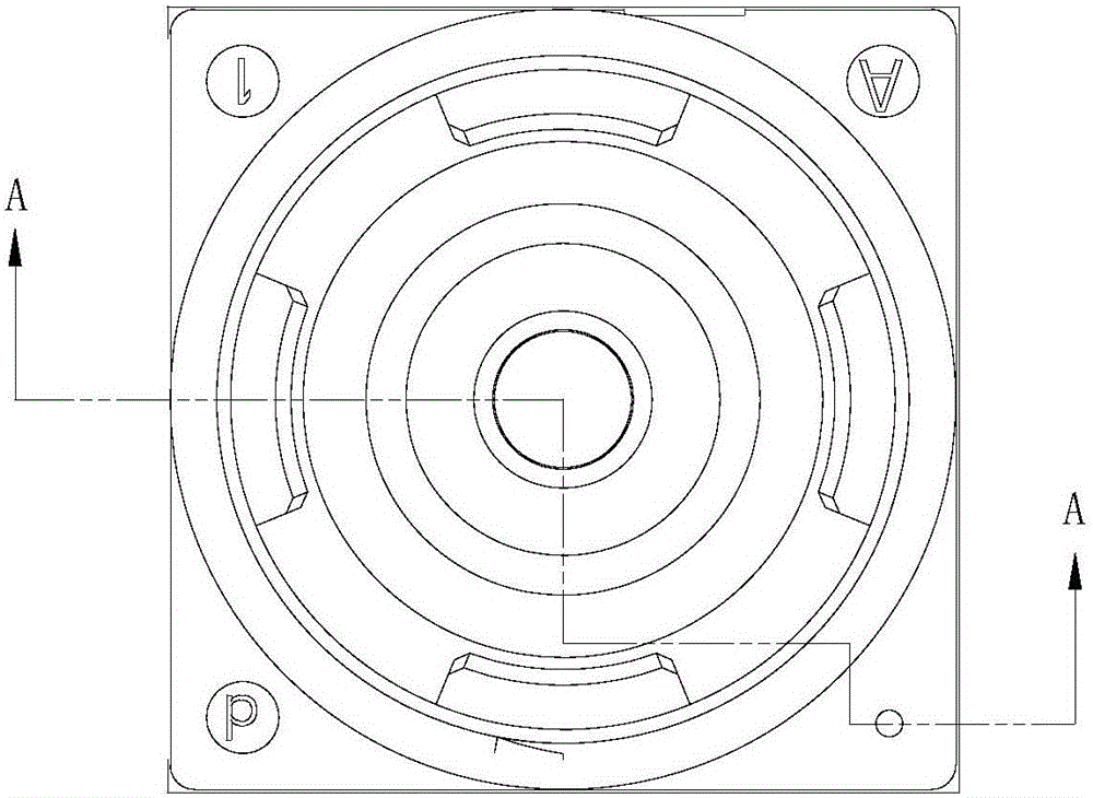
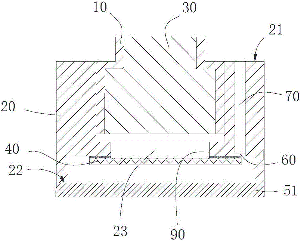
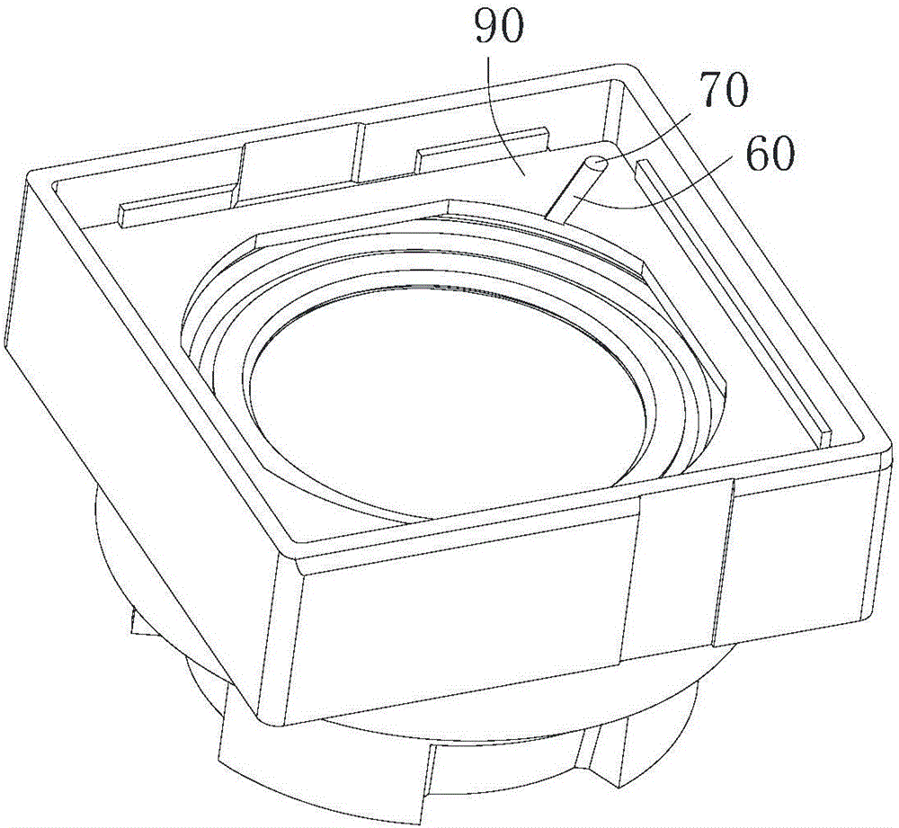
[0025] Please also see Figure 1a , 1b and 1c, other components not related to the improvement of the present invention are not shown in this figure, one embodiment of the present invention provides a camera module, the camera module includes a lens barrel 10, a lens holder 20, a lens group 30 and filter 40. The mirror base 20 has an upper surface 21 and a lower surface 22 opposite to the upper surface 21, and has an inner cavity passing through the upper and lower surfaces 21, 22, that is, the mirror base 20 is hollow, and an accommodation space is formed inside it twenty three. Part or all of the lens barrel 10 is accommodated in the lens holder 20 , and the lens group 30 is accommodated in the lens barrel 10 . In this embodiment, the lens barrel 10 and the lens holder 20...


PUM


Abstract

Disclosed in the invention is a camera module group comprising a lens barrel, a lens seat, a lens piece group, and a light filter. The lens seat has an upper surface, a lower surface, and an inner cavity penetrating the upper surface and the lower surface. One part of or the whole lens barrel is accommodated into the lens seat; and the lens barrel and the lens seat form an integrated structure. The lens piece group is accommodated into the lens barrel. The lens seat includes a boss that is arranged at the inner wall of the lens seat in a protruding mode and is located between the lens barrel and the lower surface. The light filter is fixed at the bottom of the boss; and an air discharge duct is formed in the bottom of the boss. An exhaust vent is formed in the lens seat and extends to the upper surface of the lens seat from the bottom of the boss. The air discharge duct and the exhaust vent are communicated with each other; and with the air discharge duct and the exhaust vent, the inner cavity and the external space of the lens seat are communicated. Therefore, gas caused by heating solidification glue can be exhausted outside of the camera module group timely, thereby avoiding the influence on the smoothness among all electronic elements of the camera module group. Besides, the lens barrel and the lens are in an integrated mode, so that a phenomenon that the imaging quality is affected due to chippings generated during the assembling process can be prevented.

Description

technical field [0001] The invention relates to the field of optical photography, in particular to a camera module. Background technique [0002] Electronic products such as mobile devices, computers, and electronic watches usually have a camera module, and the module usually includes a lens barrel, a lens mount, a lens set, a filter, an image sensor, and a circuit board. When assembling in the traditional process, first the filter is glued into the lens holder by glue, then the lens holder is attached to the circuit board by glue, and then the lens barrel containing the lens group and the lens holder are snapped together through threads. In this way, when the lens barrel and the lens base are fitted through the screw teeth, the falling debris will contaminate the filter, thereby affecting the image quality. And when matching the lens barrel containing the lens group with the lens base, it is necessary to carry out the focusing process on the machine, that is, to rotate the...

Claims


Application Information

Patent Timeline
Patent Type & Authority Applications(China)
IPC IPC(8): G02B7/00G02B7/02G02B7/04G03B29/00G03B30/00
Inventor 刘新建
Owner NANCHANG O FILM OPTICAL ELECTRONICS TECH CO LTD
Learn More