Optical anti-vibration voice coil motor capable of changing tilt shift centre and assembly method thereof

A technology of optical anti-shake and voice coil motor, applied in optics, optical components, camera focusing devices, etc., can solve the problems of image edge resolution reduction, increase the complexity and cost of the control system, and achieve improved reliability and simple structure , cost reduction effect

Inactive Publication Date: 2015-11-25
AP PHOTONICS SHEN ZHEN
View PDF8 Cites 22 Cited by
  • Summary
  • Abstract
  • Description
  • Claims
  • Application Information

AI Technical Summary

Problems solved by technology

However, this will lead to two problems: first, the center of the shifting axis will still be very close to the optical center, so that the optical anti-shake effect still needs to be improved; second, the distance between the center of the spring and the center of gravity of the moving structure There is a certain distance between them. When the lens faces the horizontal direction, the gravity acting on the moving structure (including the lens) will cause the center of the spring to shift and tilt, resulting in a decrease in the resolution of the edge of the image.
Therefore, this type of voice coil motor needs to use additional control methods to compensate for the tilt caused by gravity, thus increasing the complexity and cost of the control system

Method used


Image

  • Optical anti-vibration voice coil motor capable of changing tilt shift centre and assembly method thereof
  • Optical anti-vibration voice coil motor capable of changing tilt shift centre and assembly method thereof
  • Optical anti-vibration voice coil motor capable of changing tilt shift centre and assembly method thereof

Examples


Embodiment Construction

[0045] In order to make the object, technical solution and advantages of the present invention clearer, the present invention will be further described in detail below in conjunction with the accompanying drawings and embodiments. It should be understood that the specific embodiments described here are only used to explain the present invention, not to limit the present invention.

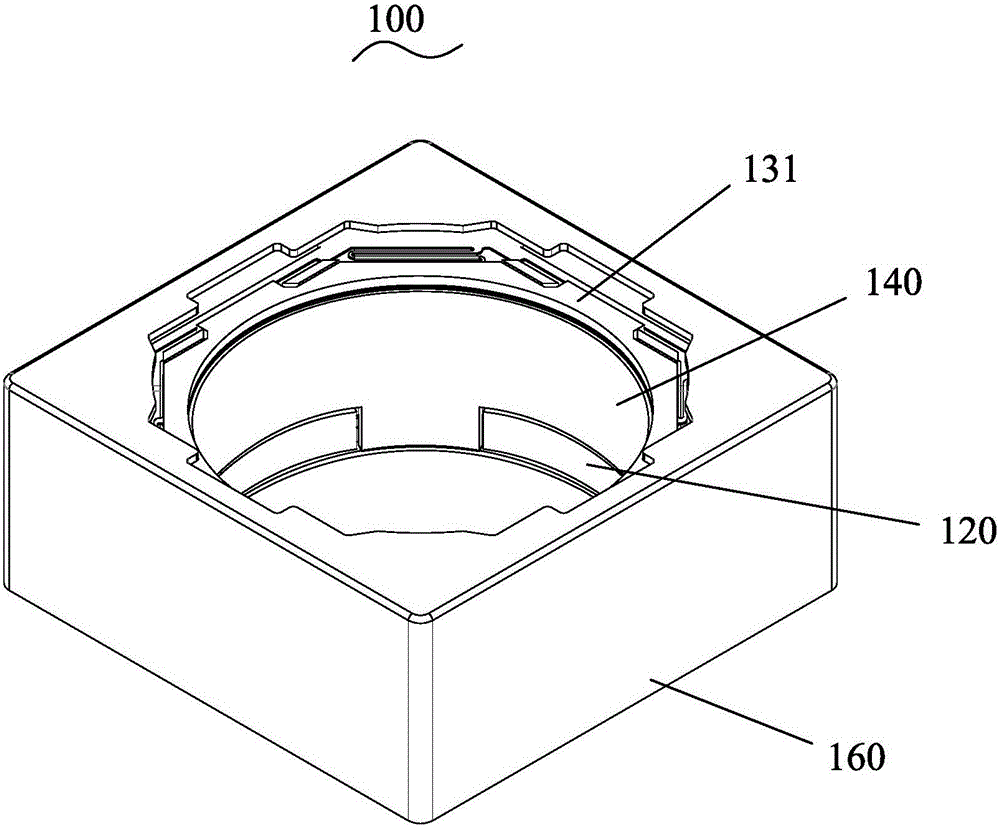
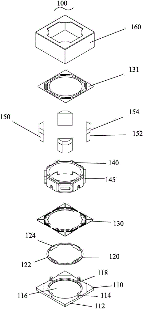
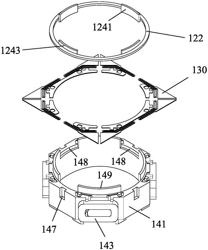
[0046] see Figure 1 to Figure 4 As shown, the optical anti-shake voice coil motor 100 capable of changing the shifting center provided by the first embodiment of the present invention includes a base 110, a pressure ring 120, a first elastic piece 130, a lens carrier 140, a magnet group 150, a second elastic piece 131 and Housing 160. Wherein, the pressure ring 120 , the first elastic piece 130 , the lens carrier 140 , the second elastic piece 131 and the magnet group 150 are all located in the box formed by the base 110 and the housing 160 .

[0047] Specifically, the base 110 includes a base ...


PUM


Abstract

The invention provides an optical anti-vibration voice coil motor capable of changing tilt shift centre, comprising a substrate, at least one elastic sheet, a lens carrier, at least three magnetic body groups and a shell. The pedestal, the shell and the magnetic body groups are connected together to form a fixed structure. The magnetic body groups are arranged in the shell; the lens carrier comprises a main body and coils arranged on the main body. The number of the coils is the same as that of the magnetic body groups. The coils and the magnetic body groups are arranged oppositely one by one. The elastic sheet is connected with the lens carrier and the magnetic body groups to form a multi-variant spring oscillator system with a spring centre. The elastic sheet is electrically connected with the coils. The direction of the electromagnetic resultant force of each coil is not faced to and not back to the spring centre, and is not parallel to an optical axis. By adjusting the size of each resultant force, the motor could be used for controlling the tilt shift of the lens to be tilted and be moved along the optical axis to achieve an optical anti-vibration function and an automatic focusing function. By adopting the above structure, the optical anti-vibration voice coil motor not only is simple in structure, and high in reliability, and reduces production cost, but also could maintain excellent image resolution and resist magnetic disturbance.

Description

technical field [0001] The invention belongs to the technical field of optical anti-shake devices, and in particular relates to an optical anti-shake voice coil motor capable of changing the shift center and an assembly method thereof. Background technique [0002] Today's miniature optical image stabilization voice coil motor technology has been widely used in high-end mobile phones, which can effectively reduce the chance of blurry photos taken in low-light environments, and reduce the disturbing shake in videos. However, compared with general auto-focus motors, anti-shake voice coil motors are more complex in design, lower in production yield and efficiency, and higher in cost. Therefore, described technology has not yet been popularized to mid-end and low-end mobile phones, and most mobile phone users still fail to enjoy the benefits brought by this technology. [0003] Miniature optical image stabilization voice coil motors can be divided into three categories: camera ...

Claims


Application Information

Patent Timeline
Patent Type & Authority Applications(China)
IPC IPC(8): H02K33/18H02K15/00G02B7/09G03B3/00
Inventor 麦练智卢伟光
Owner AP PHOTONICS SHEN ZHEN
Why Eureka
Try Eureka