Imaging module and manufacturing method thereof

The technology of an imaging module and its manufacturing method is applied in the directions of image communication, telephone structure, television, etc., which can solve the problems of large volume of imaging module and lateral movement of moving components, etc., and achieve small size, no electromagnetic interference, and light weight Effect

Active Publication Date: 2021-05-28
NINGBO SEMICON INT CORP
View PDF4 Cites 0 Cited by
  • Summary
  • Abstract
  • Description
  • Claims
  • Application Information

AI Technical Summary

Problems solved by technology

[0003] The purpose of the present invention is to provide an imaging module and its manufacturing method, which can solve the problems of large volume of the imaging module and lateral movement of the moved components

Method used


Image

  • Imaging module and manufacturing method thereof
  • Imaging module and manufacturing method thereof
  • Imaging module and manufacturing method thereof

Examples


Embodiment 1

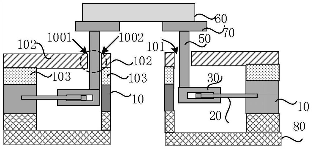
[0045] figure 1 It is a schematic structural diagram of an imaging module according to an embodiment of the present invention, Figure 2A for figure 1 For a top view, please refer to figure 1 and Figure 2A , the imaging module includes:

[0046] The moved element 60, the moved element 60 includes a lens group, an imaging sensing element, an aperture or a lens sheet;

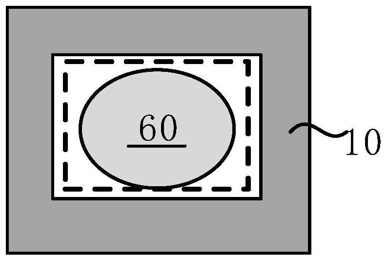
[0047] at least one support block 10, the at least one support block encloses a space above which the moved element 60 is suspended;

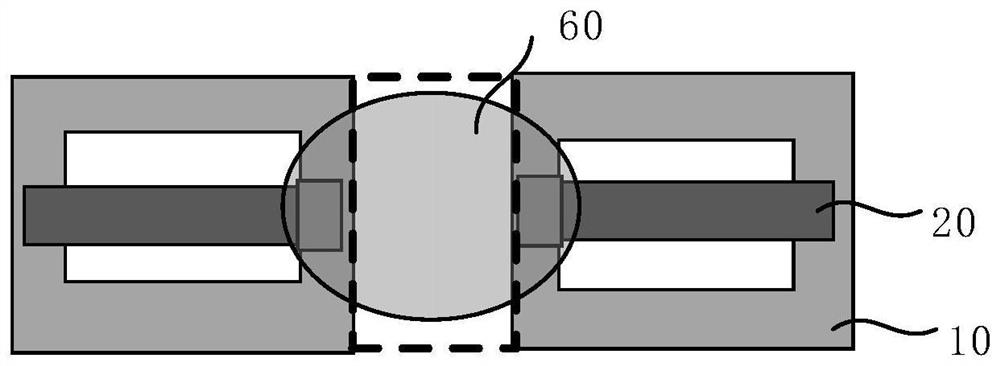
[0048] At least two piezoelectric elements 20, including a movable end and a fixed end, the fixed end is fixed to the support block 10, and the movable end is at least partially located in the limiting groove 30; the at least two piezoelectric elements 20 are distributed on the periphery of the moved element 60;

[0049] A connecting arm 50, one end of which is connected to the moved element 60, and the other end is connected to the limiting groove 30;

[0050] The lateral...

Embodiment 2

[0072] refer to Figure 13 , the support blocks 10 are a pair, symmetrically distributed on both sides of the moved element 60, each support block 10 is provided with a piezoelectric element 20 on the upper surface, two piezoelectric elements 20 are symmetrically arranged, and the connecting arm 50 is arranged along the piezoelectric Two vertical first walls 104A and second walls 104B are provided on both sides of the element 20 in the length direction, and the two vertical first walls 104A and second walls B are respectively used as lateral movement limiters. The first side wall and the second side wall, the distance between the two vertical first walls 104A and the second wall 104B is slightly larger than the outer diameter of the connecting arm 50, when the piezoelectric element 20 warps, the piezoelectric element 20 The movable end of the electrical element 20 drives the connecting arm 50 through the limiting groove 30, and the connecting arm 50 drives the moved element 60...

Embodiment 3

[0075] refer to Figure 14 , the support block 10 is a pair, symmetrically distributed on both sides of the moved element 60, the support block 10 includes two sub-support blocks in the up and down direction, and the piezoelectric element 20 is fixed between the two sub-support blocks. The lateral movement limiter is a first upper cover 105 with a first opening 106 arranged on the upper surface of the support block 10. One end of the connecting arm 50 is connected to the limit groove 30 through the first opening 106, and the other end is connected to the moving position. On the lower surface of the element 60, the shape of the first opening 106 matches the connecting arm 50, and the size is slightly larger than the outer diameter of the connecting arm 50. The two inner walls of the first opening 106 that limit the lateral movement of the connecting arm 50 serve as lateral movement limiters. The first side wall and the second side wall of the piece. In this embodiment, each su...


PUM


Abstract

The invention discloses an imaging module and a manufacturing method thereof. The imaging module comprises a moved element; a space is defined by the at least one supporting block, and the at least one supporting block is hung above the space by the moving element; the piezoelectric elements are distributed on the periphery of the moved element, each piezoelectric element comprises a movable end and a fixed end, the fixed ends are fixed to the supporting blocks, and at least parts of the movable ends are located in the limiting grooves; the at least two piezoelectric elements are distributed on the periphery of the moved element; one end of the connecting arm is connected with the moved element and the other end is connected with the limiting groove; the transverse movement limiting part comprises a first side wall and a second side wall which are located on the two sides of the connecting arm, and the first side wall and the second side wall are distributed in the radial direction parallel to the moved element; and the external signal connecting end is electrically connected with an electrode in the piezoelectric element, and when the piezoelectric element is in a power-on state, the movable end drives the moved element to move upwards or downwards through the connecting arm.

Description

technical field [0001] The invention relates to the technical field of motion control, in particular to an imaging module and a manufacturing method thereof. Background technique [0002] In some electronic terminals, it is usually necessary to make some parts thereof translate, move vertically or tilt, so as to realize some special functions. For example, in various electronic terminals such as video cameras, cameras, and mobile phones with lens modules, a driving mechanism such as a VCM motor (Voice Coil Actuator / Voice Coil Motor) is usually used to make the movable lens or image sensor , shift in the direction of the optical axis to focus or zoom, or shift in a direction perpendicular to the direction of the optical axis to prevent optical shake. However, unlike traditional SLR cameras, it is a huge engineering challenge to implement this function in electronic terminals such as mobile phones, miniature cameras, and cameras with small spaces. Therefore, a structure for ...

Claims


Application Information

Patent Timeline
Patent Type & Authority Applications(China)
IPC IPC(8): H04M1/02H04N5/225
CPCH04M1/0264H04N23/54H04N23/57H04N23/55
Inventor 黄河桂珞向阳辉
Owner NINGBO SEMICON INT CORP
Why Eureka
Try Eureka