Digging bit

一种钻头、扩孔部的技术,应用在钻头、土方钻采、钻井设备等方向,能够解决挖掘阻力增大、砂土堵塞于大径部与孔壁之间、不易等问题,达到促进排出的效果

Inactive Publication Date: 2015-11-25
RYUKI PRECISION TOOLS CO LTD
View PDF11 Cites 2 Cited by
  • Summary
  • Abstract
  • Description
  • Claims
  • Application Information

AI Technical Summary

Problems solved by technology

[0007] However, in this type of retractable drill, grooves are formed on the large-diameter portion at the rear end of the skirt as described above. The debris discharge performance is reduced, which may lead to an increase in excavation resistance when forming an excavation hole.
Moreover, when the drill body is pulled out from the excavation hole, sand and soil may be blocked between the large-diameter portion and the hole wall, and if sand and soil remain in the part between the large-diameter portion and the reaming portion of the skirt , it is not easy to effectively discharge the retained sand from the debris groove, and thus, it may not be possible to retract the drill body

Method used


Image

  • Digging bit
  • Digging bit
  • Digging bit

Examples


Embodiment Construction

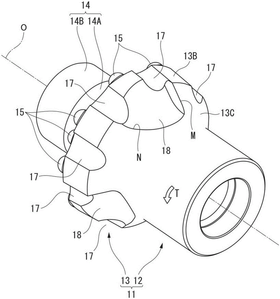
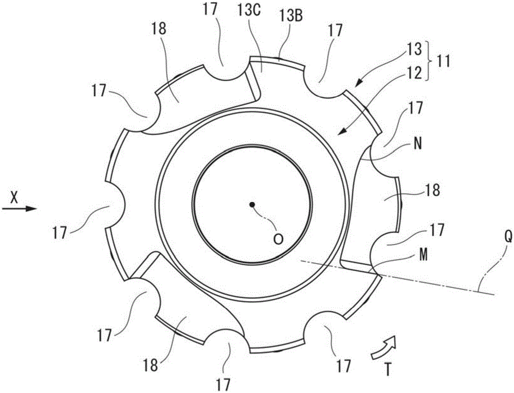
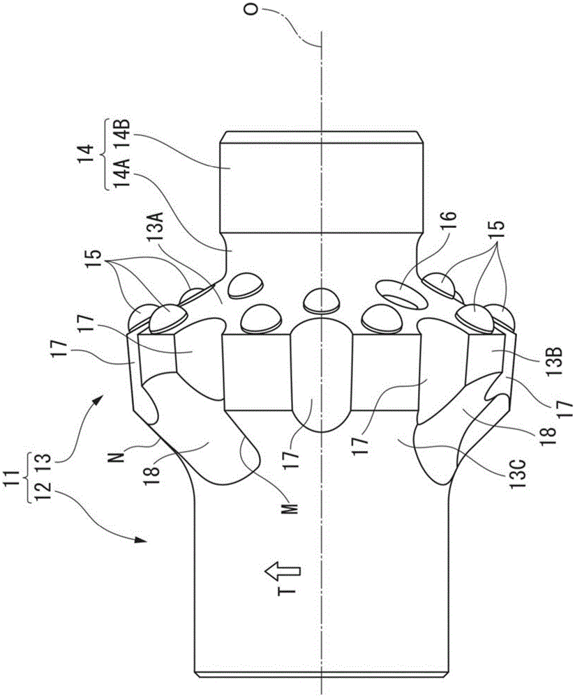
[0033] Figure 1 to Figure 3 It is a figure which shows 1st Embodiment of this invention. The excavation drill according to the present embodiment is called a reamer, and is inserted into a pre-formed small-diameter excavation hole to expand the excavation hole to a large diameter. In the present embodiment, the drill body 11 is integrally formed of a metal material such as steel, and has a substantially bottomed multistage cylindrical shape centered on the axis O. As shown in FIG.

[0034] The rear end of the drill body 11 ( figure 1 Middle is the lower right part, image 3 The center is the left part) is a cylindrical skirt 12 with a constant outer diameter, and at the front end side of the skirt 12 ( figure 1 Middle is the upper left side, image 3(center is the right side) is formed with an enlarged hole portion 13 having a larger outer diameter than the skirt portion 12 . In addition, on the front end side of the reaming portion 13 , a pilot portion 14 having a diame...


PUM


Abstract

A reaming section (13) is provided at the front end of a bit body (11) which is rotated about an axis (O), and the reaming section (13) has a greater diameter than the rear end of the bit body (11). Digging tips (15) are arranged at the front end of the reaming section (13). Earth discharge grooves (17) extending in the direction of the axis (O) are formed in the outer periphery of the reaming section (13). Connection grooves (18) connecting to the earth discharge grooves (17) are formed so as to extend from the outer periphery of the reaming section (13) to the rear end.

Description

technical field [0001] The present invention relates to an excavation drill for forming an excavation hole in a rock plate or the like by disposing an excavation blade at a front end portion of a drill body which rotates around an axis. [0002] This application claims priority based on Patent Application No. 2013-043549 filed in Japan on March 5, 2013 and Patent Application No. 2014-021674 filed in Japan on February 6, 2014, and uses the contents thereof here. Background technique [0003] In such a drilling operation using the excavation drill, after the excavation hole is formed to a predetermined depth, the drill main body is pulled out from the excavation hole and retracted. However, when an excavation hole is formed from a highly disintegrable bedrock, the hole wall of the excavation hole collapses and sand and soil remain on the rear end side of the drill body, and the drill body may not be pulled out from the excavation hole. Therefore, in this case, for example, as...

Claims


Application Information

Patent Timeline
Patent Type & Authority Applications(China)
IPC IPC(8): E21B10/36
CPCE21B10/26E21B10/38E21B10/60
Inventor 中村和由太田博士
Owner RYUKI PRECISION TOOLS CO LTD
Why Eureka
Try Eureka