A positioning fixture for lathe processing

A technology for positioning fixtures and lathe processing, which is applied in the field of lathes to achieve the effect of avoiding deformation of parts and facilitating parts processing

Active Publication Date: 2017-09-29
WUHU HENGLONG AUTO STEERING SYST
View PDF6 Cites 0 Cited by
  • Summary
  • Abstract
  • Description
  • Claims
  • Application Information

AI Technical Summary

Problems solved by technology

[0003] The technical problem to be solved by the present invention is to provide a positioning fixture for lathe processing to achieve accurate positioning of ring parts and facilitate the processing of ring parts while avoiding deformation of the parts.

Method used


Image

  • A positioning fixture for lathe processing
  • A positioning fixture for lathe processing

Examples


Embodiment Construction

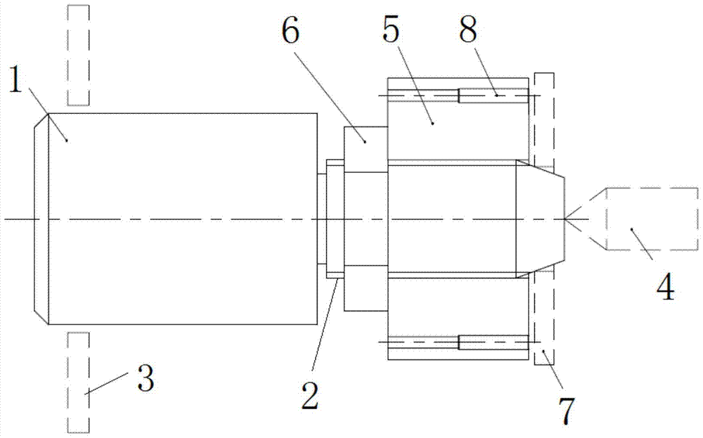
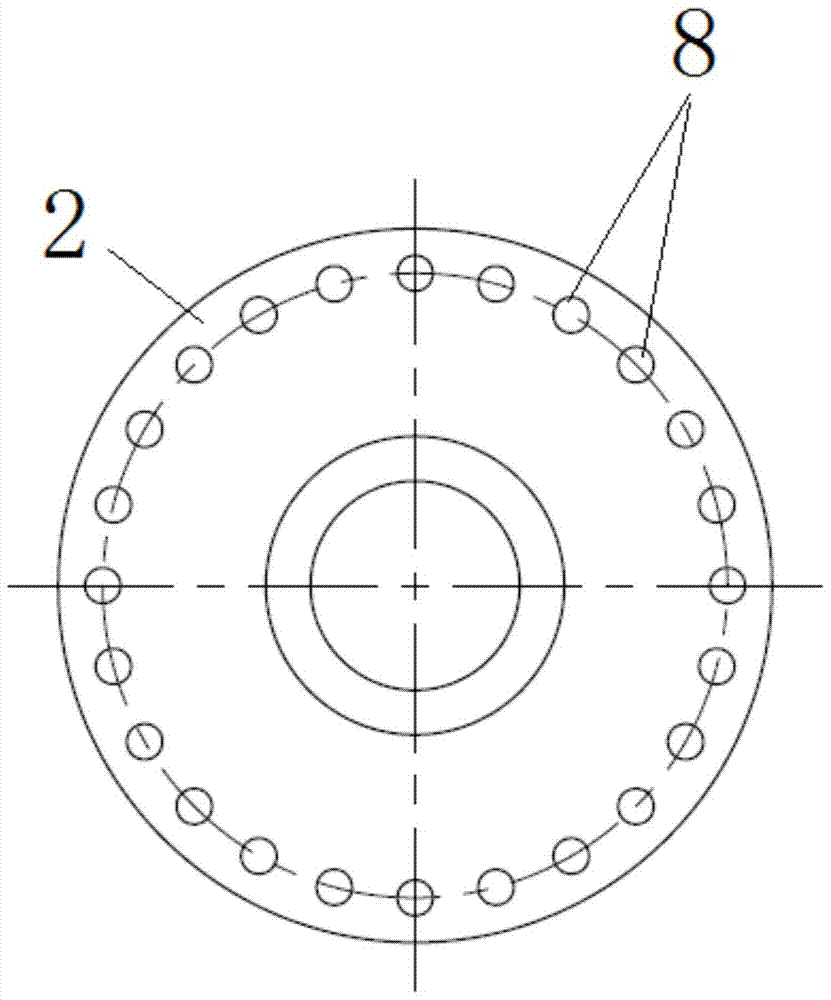
[0016] Such as Figure 1 ~ Figure 2 A positioning fixture for lathe processing is shown, including an aligning positioning rod, and the aligning positioning rod includes a connected positioning rod 1 and an adjusting rod 2. The positioning rod 1 is connected with the three-jaw chuck 3 of the lathe, and the adjusting rod 2 ends There is a lathe top 4 on the side of the head, one end of the adjustment rod 2 of the self-aligning positioning rod is connected with the positioning rod 1, and the side wall of the other end is a conical surface, which is convenient for the displacement of the workpiece on the conical surface. The adjustment rod 2 is sleeved with a rotating positioning disc 5, and a locking nut 6 sleeved on the adjusting rod 2 is provided between the inner end surface of the rotating positioning disc 5 and the positioning rod 1, and a locking nut 6 is provided on the outer end surface of the rotating positioning disc 5. A magnet 8 that attracts a workpiece 7.

[0017]...


PUM


Abstract

The invention discloses a positioning fixture for lathe machining. The positioning fixture includes an aligning positioning rod which includes a positioning rod and an adjusting rod, wherein the positioning rod and the adjusting rod are connected. The positioning rod is connected to a three-jaw chuck of a lathe. A side at an end portion of the adjusting rod is provided with a lathe center. The adjusting rod of the aligning positioning rod has one end connected to the positioning rod and the other end which has a side wall shaped in a conical surface. The adjusting rod is sleeved with a rotary positioning disc. An inner end surface of the rotary positioning disc and the positioning rod are provided therebetween with a locking nut which sleeves the adjusting rod. The outer end surface of the rotary positioning disc is provided thereon with a magnet which attracts a workpiece. According to the invention, with the structure, the positioning fixture has the following advantages: 1. the rotation of the rotary positioning disc drives the workpiece to displace on the conical surface of the adjusting rod, the center of the workpiece is adjusted to a rotation center of the lathe, and accurate positioning is performed on annular parts; 2. the rotary positioning disc is locked by the locknut so as to achieve axial positioning and radial positioning of the workpiece and prevent part deformation caused by the positioning of the three-jaw chuck of the lathe, and thus parts are convenient to machine.

Description

technical field [0001] The invention relates to the technical field of lathes, in particular to a positioning fixture for lathe processing. Background technique [0002] Existing ordinary lathes and CNC machine tools usually use three-jaw chucks to position parts. If this method is used to position ring parts, it will cause deformation of the parts, and the tool will interfere with the three-jaw chuck, making it impossible to process. Component. It is a problem to be solved in the prior art to accurately locate the ring parts, avoid deformation of the parts, and facilitate the processing of the parts. Contents of the invention [0003] The technical problem to be solved by the present invention is to provide a positioning fixture for lathe processing to achieve accurate positioning of ring parts and facilitate the processing of ring parts while avoiding deformation of the parts. [0004] In order to solve the above-mentioned technical problems, the technical solution of ...

Claims


Application Information

Patent Timeline
Patent Type & Authority Patents(China)
IPC IPC(8): B23Q3/00
CPCB23Q3/00
Inventor 伍和龙鲁秀伟江火文
Owner WUHU HENGLONG AUTO STEERING SYST
Why Eureka
Try Eureka