Propeller type wind tunnel electrocar
A propeller, electric vehicle technology, applied in the field of electric vehicles
- Summary
- Abstract
- Description
- Claims
- Application Information
AI Technical Summary
Problems solved by technology
Method used
Image
Examples
no. 1 example
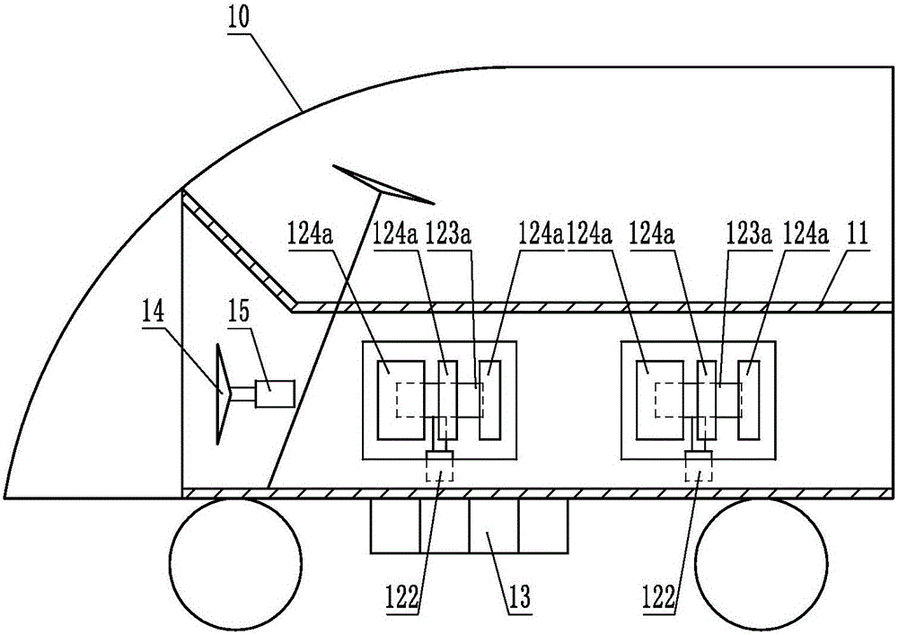
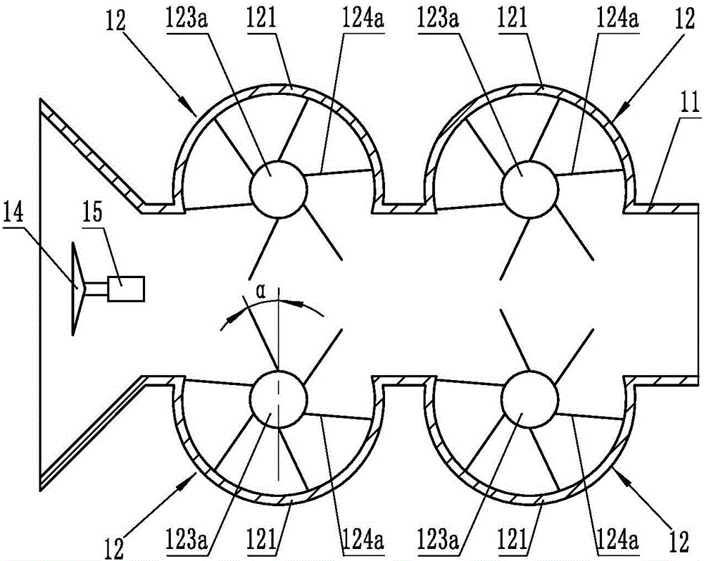
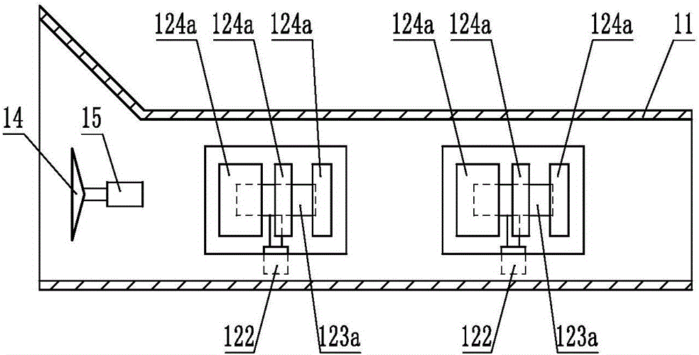
[0025] Depend on figure 1 , figure 2 and image 3 It can be seen that the propeller-type wind tunnel electric vehicle includes a car body 10 and a wind tunnel power generation device fixedly connected to the car body 10. The wind tunnel power generation device includes an air duct 11, and the air inlet of the air duct 11 is arranged at the front end of the car body 10. A power generation unit 12 is provided on the outside of the air duct 11, the power generation unit 12 includes a housing 121 fixedly connected to the side wall of the air duct 11 and communicated with the inner cavity of the air duct 11, a generator 122 and a generator set in the inner cavity of the housing 121. blade device, the blade device includes a connector fixedly connected to the input shaft of the generator 122, in this embodiment, the connector is a disc 123a, and blades 124a arranged at intervals along the circumference of the disc 123a, in this embodiment Among them, the blade 124a is a plate-sha...
no. 2 example
[0030] Depend on Figure 4 It can be seen that this embodiment is basically the same as the first embodiment, the differences are:
[0031] The connecting piece is the shaft sleeve 123b, and the blades 124a are arranged at intervals along the circumference of the shaft sleeve 123b. There is an angle α between the blade 124a and the shaft sleeve 123b in the radial direction, 10°≤angle α≤70°, and the blades 124a are located in the housing 121 When the position communicates with the inner cavity of the air duct 11 , the blade 124 a is inserted into the inner cavity of the air duct 11 away from the side of the sleeve 123 b, and the blade 124 a is obliquely directed to the air inlet of the air duct 11 .
no. 3 example
[0033] Depend on Figure 5 , Figure 6 It can be seen that this embodiment is basically the same as the first embodiment, the differences are:
[0034] The blade device includes a connector fixedly connected to the input shaft of the generator 122. In this embodiment, the connector is a disk 123a, and blades 124b are arranged at intervals along the circumference of the disk 123a. The connected first half piece 124b1, the second half piece 124b2 fixedly connected to the side of the first half piece 124b1 away from the disc 123a, the angle β between the first half piece 124b1 and the second half piece 124b2, 0°
PUM
 Abstract
Description
Claims
Application Information
 - R&D
- Intellectual Property
- Life Sciences
- Materials
- Tech Scout
- Unparalleled Data Quality
- Higher Quality Content
- 60% Fewer Hallucinations
Browse by: Latest US Patents, China's latest patents, Technical Efficacy Thesaurus, Application Domain, Technology Topic, Popular Technical Reports.
© 2025 PatSnap. All rights reserved.Legal|Privacy policy|Modern Slavery Act Transparency Statement|Sitemap|About US| Contact US: help@patsnap.com


