Energy-saving vehicle brake device

A vehicle braking and energy-saving technology, applied in the direction of brakes, braking components, vehicle components, etc., can solve the problems of shortening the service life of tires and road surfaces, braking tires and road surface damage, waste of heat of wheels, etc., and achieves the design structure. Simple and reasonable, prolong the service life, avoid the effect of side slip

Inactive Publication Date: 2015-12-02
王刚
View PDF0 Cites 8 Cited by
  • Summary
  • Abstract
  • Description
  • Claims
  • Application Information

AI Technical Summary

Problems solved by technology

[0002] At present, the vehicle braking device is mainly a brake pad device utilizing the friction principle, which mainly has the following problems: 1. During the friction braking process, the kinetic energy of the wheel is converted into heat and is wasted
2. During the braking process, the lateral force in the forward direction of the vehicle is likely to cause the vehicle to slip
4. Both the tires and the road surface of the brake system are damaged, which shortens the service life of the tires and the road surface. In summary, the existing vehicle braking device should be improved

Method used


Image

  • Energy-saving vehicle brake device
  • Energy-saving vehicle brake device
  • Energy-saving vehicle brake device

Examples


Embodiment 1

[0042] Embodiment 1 (being applicable to automobile etc.)

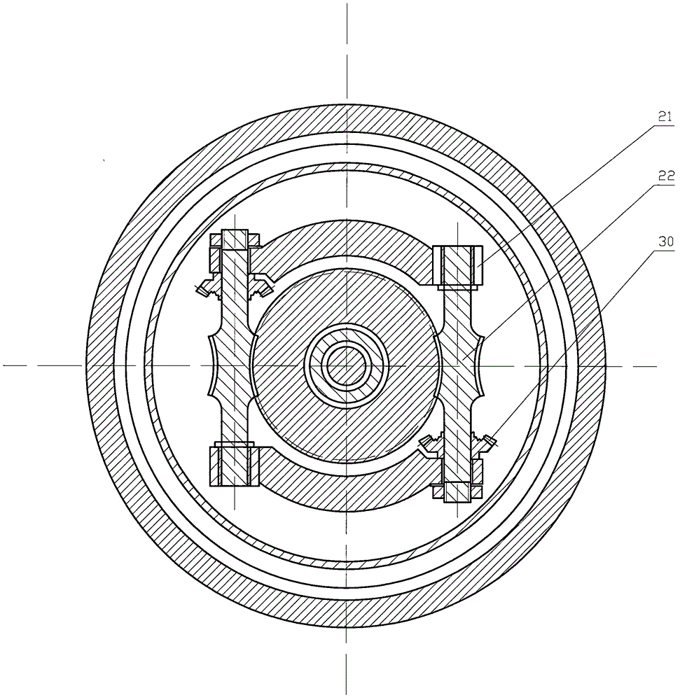
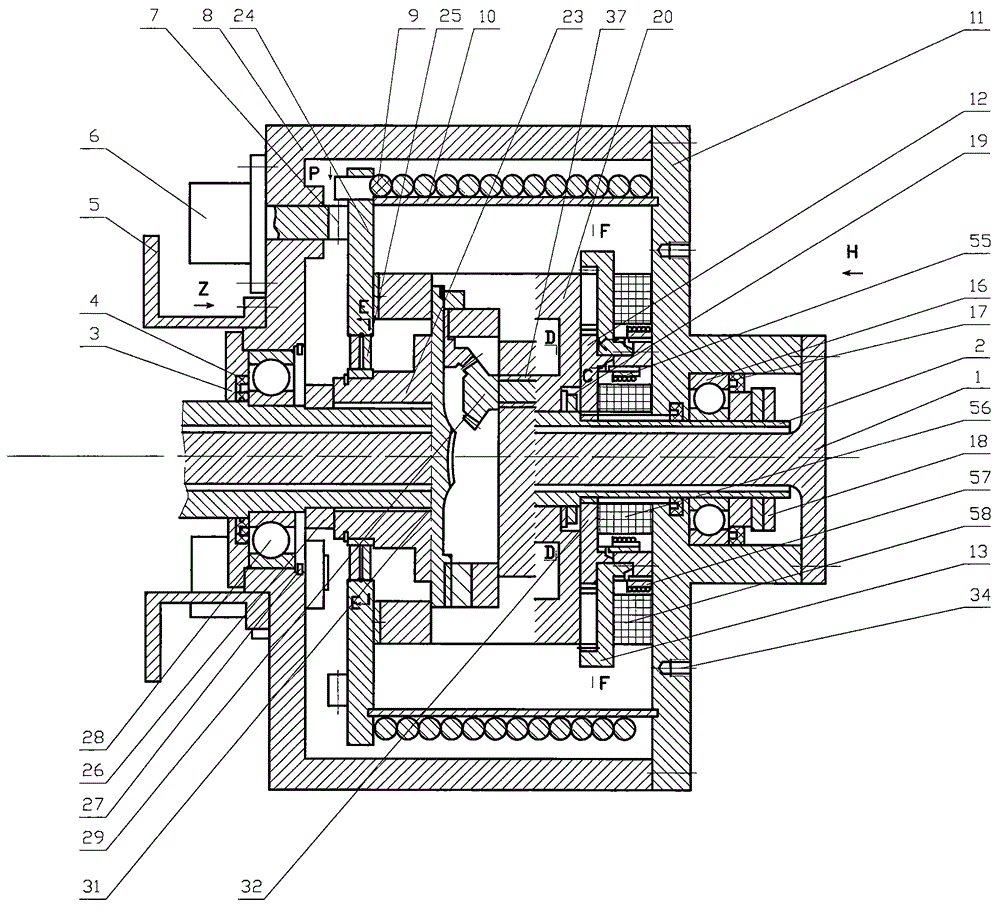
[0043] Such as figure 1 As shown in -13, the energy-saving vehicle braking device includes a power input and output part assembled on the axle shaft sleeve 2, a deceleration part, a torsion spring part, a housing, a bearing and ancillary parts. The housing consists of a front cover 11 and rear cover 8 are formed and fixed by bolts, the outer side of front cover 11 is provided with a bolt hole 34 for connecting the tire hub, the outside of the half shaft 1 is provided with a half shaft sleeve 2, and the front end of the half shaft 1 is disc-shaped and front. Cover 11 is connected and fixed. The front cover 11 and the rear cover 8 are respectively supported on the half-shaft casing by the front and rear bearings 16 and 28. Oil seals 17 are provided on the inside and outside of the front bearing, and are locked and positioned by lock nuts 18. An oil seal is provided on the outside of the rear bearing 28. 3 and sealing ...

Embodiment 2

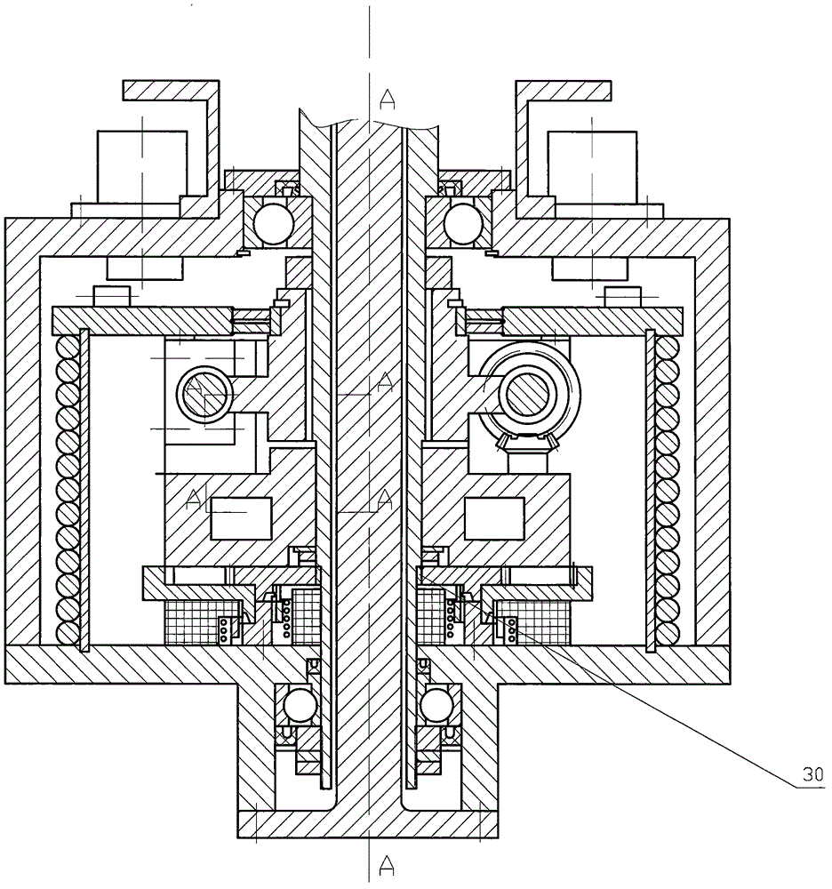
[0052] Embodiment 2 (applicable to trains, etc.) such as Figure 12 The energy-saving vehicle braking device of Fig. 17 includes the power input and output part assembled on the axle shaft 63, the speed reducer part, the torsion spring part, the housing, the bearing and the accessory part are different from the automobile in that the semi-axle sleeve is eliminated.

[0053] The power input and output part and the reducer part housing, bearing and accessory parts are basically the same as those in Embodiment 1, and will not be described in detail.

[0054] There are two sets of elastic force input and output parts, including the elastic force input and output part for forward braking and the elastic force input and output part for reverse braking. Direction opposite overrunning clutch 48, the spring knot hand 38 that is driven by overrunning clutch, the outer periphery of described spring knot hand 38 is provided with a groove, and described torsion spring part is the torsion s...


PUM


Abstract

The invention relates to an energy-saving vehicle brake device which is characterized by comprising a power input and output part on a vehicle semi-axle, an elasticity input and output part, a speed reducer part, a torsion spring part, a shell bearing and accessory parts. The energy-saving vehicle brake device is reasonable in structural design and safe and reliable in use and radically solves the problems that the existing brake pad device utilizing the friction principle wastes energy consumption potential safety hazards exist and tires and pavements are easy to wear; and the torsion spring is used for realizing brake as well as storage and utilization of the energy consumption.

Description

Technical field: [0001] The invention relates to a braking device in the traffic field, in particular to an energy-saving vehicle braking device capable of recovering and utilizing most of the energy consumption in the braking process. Background technique: [0002] At present, the vehicle brake device is mainly a brake pad device utilizing the principle of friction, which mainly has the following problems: 1. During the friction braking process, the kinetic energy of the wheel is converted into heat and wasted in vain. 2. During the braking process, the lateral force in the forward direction of the vehicle is likely to cause the vehicle to skid. 3. Braking on icy and snowy roads, causing the vehicle to slip. 4. Both the tires and the road surface of the brakes are damaged, which shortens the service life of the tires and the road surface. In summary, the existing vehicle braking device should be improved. Invention content: [0003] The object of the present invention i...

Claims


Application Information

Patent Timeline
Patent Type & Authority Applications(China)
IPC IPC(8): B60T1/10
CPCB60T1/10
Inventor 王刚王晓兰王晓博
Owner 王刚
Why Eureka
Try Eureka