Infusion pipe conveying mechanism

A transmission mechanism and infusion tube technology, applied in the direction of conveyors, mechanical conveyors, conveyor objects, etc., can solve the problems of reduced production efficiency, work fatigue, unfavorable operation, etc., achieve smooth transmission process, improve service life, and solve problems easy winding effect

Active Publication Date: 2015-12-02
HUAZHONG UNIV OF SCI & TECH
View PDF6 Cites 17 Cited by
  • Summary
  • Abstract
  • Description
  • Claims
  • Application Information

AI Technical Summary

Problems solved by technology

On the infusion tube production line, it is generally necessary to load the raw materials such as the infusion tube body and put them into the air leakage test device for air leakage detection. Put it into the prepared packaging bag, it does not need to be sterilized again when using it, and it can be used just by unpacking it. It can be seen that the process of transmission involved in the production and packaging of infusion tubes is very important and very complicated
[0003] At present, the feeding of medical infusion tubes is done manually by workers. This feeding method is easy to attach germs, and often requires strict disinfection of packaging workers. At the same time, it must be operated in a huge sterile purification workshop, which requires consumption Lots of energy and production space
In addition, manual feeding of infusion tubes, in the case of large demand, workers have high work intensity, which is easy to cause work fatigue and reduce production efficiency
Since the infusion tube is a flexible plastic tube, in the case of mass production and packaging, the tubes are easily entangled, which is not conducive to operation

Method used


Image

  • Infusion pipe conveying mechanism
  • Infusion pipe conveying mechanism
  • Infusion pipe conveying mechanism

Examples


Embodiment Construction

[0028] In order to make the object, technical solution and advantages of the present invention clearer, the present invention will be further described in detail below in conjunction with the accompanying drawings and embodiments. It should be understood that the specific embodiments described here are only used to explain the present invention, not to limit the present invention. In addition, the technical features involved in the various embodiments of the present invention described below can be combined with each other as long as they do not constitute a conflict with each other.

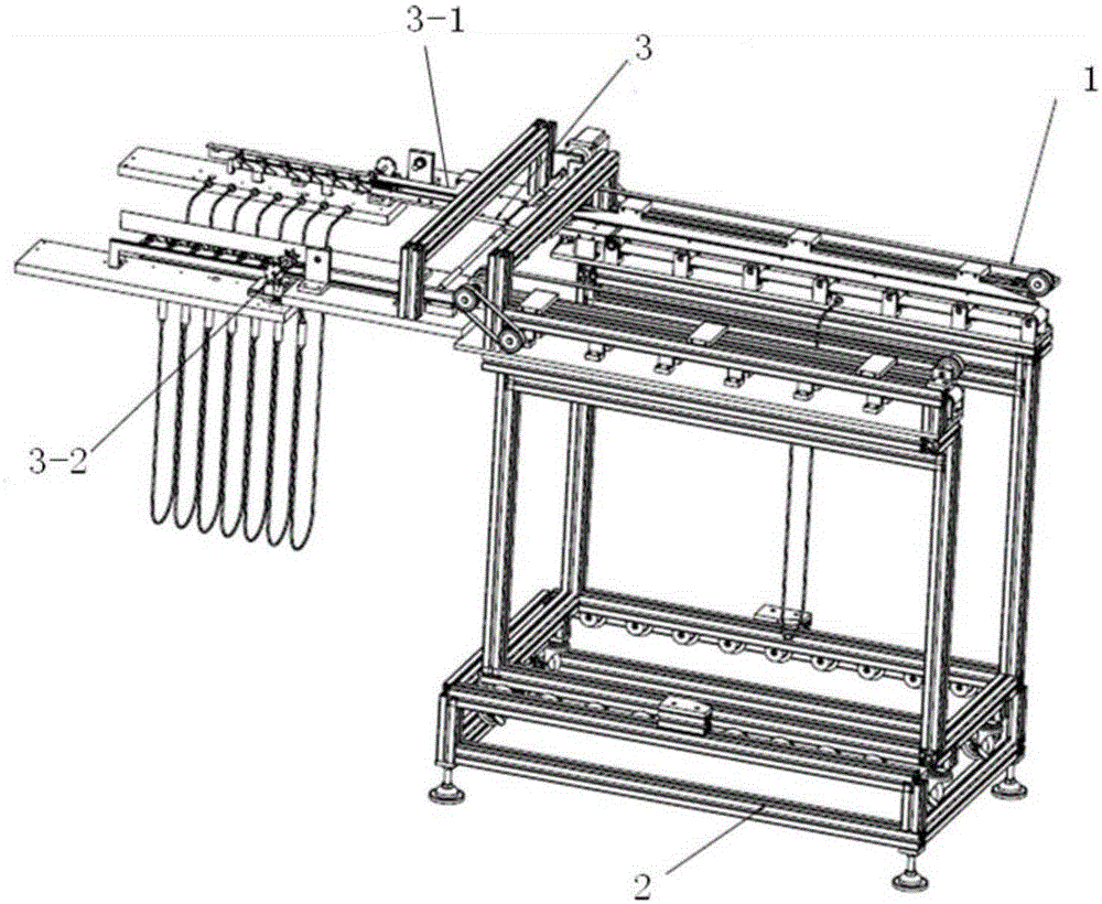
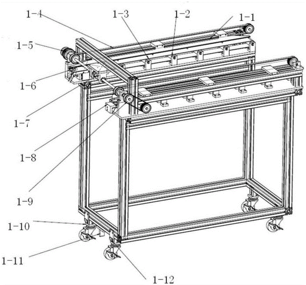
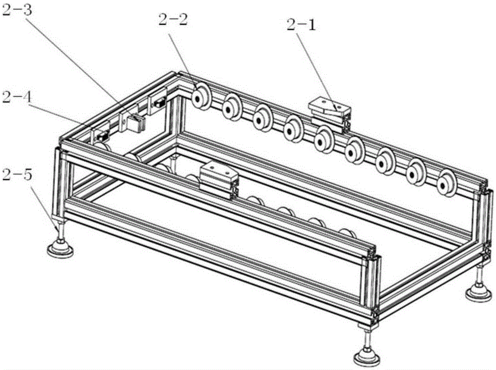
[0029] According to one embodiment of the present invention, such as figure 1 As shown, it is a schematic diagram of the overall structure of the transmission mechanism realized according to the present invention, wherein the transmission mechanism includes the following main parts: a charging mechanism 1, a charging mechanism limiting device 2 and a storage mechanism 3, wherein the charging mec...


PUM


Abstract

The invention discloses an infusion tube conveying mechanism. The infusion tube conveying mechanism comprises a loading mechanism and a storage mechanism in butt joint with the loading mechanism, the loading mechanism is used for feeding and conveying infusion tubes, and the storage mechanism is used for separating the infusion tubes conveyed from the loading mechanism to enable the infusion tubes to be arranged at preset intervals. The infusion tube conveying mechanism further comprises a loading mechanism limiting device which is arranged at the bottom of the loading mechanism and used for supporting the loading mechanism. According to the infusion tube conveying mechanism, separating operation and the like are carried out on the automatically-conveyed infusion tubes through a separating mechanism, and the problem that the tubes are likely to be wound is solved, so that subsequent packaging operation is more convenient. The butt joint mode of the ingeniously-designed separating mechanism and a loading trolley is adopted, so that the conveying process of the infusion tubes is smoother. The arrangement mode of a limiting mechanism is adopted in the design of the loading trolley, so that friction of trundles is avoided, and the service life of the loading mechanism is prolonged.

Description

technical field [0001] The invention belongs to the field of transfusion tube processing, and more specifically relates to a transfusion tube transmission mechanism. Background technique [0002] In the medical field, disposable infusion tubes are often used. The infusion tube is generally composed of a drip funnel assembly, a catheter, a puncturer, a liquid medicine filter, a flow regulator, and an intravenous needle. On the infusion tube production line, it is generally necessary to load the raw materials such as the infusion tube body and put them into the air leakage test device for air leakage detection. Putting it into the prepared packaging bag, it does not need to be sterilized again when it is used, and it can be used just by unpacking it. It can be seen that the process of transmission involved in the process of producing and packaging the infusion tube is very important and very complicated. [0003] At present, the feeding of medical infusion tubes is done manua...

Claims


Application Information

Patent Timeline
Patent Type & Authority Applications(China)
IPC IPC(8): B65G35/00B65G41/00B65G47/22B65G47/44
Inventor 胡友民丰波吴波谷勇李晨光吕丽红梁汉高扬
Owner HUAZHONG UNIV OF SCI & TECH
Why Eureka
Try Eureka