Fiber welding method and device

An optical fiber fusion splicing and optical fiber technology, applied in the field of optical fiber, can solve the problems of fiber core dislocation, optical fiber transmission loss, etc.

Active Publication Date: 2015-12-02
武汉创鑫激光科技有限公司
View PDF6 Cites 3 Cited by
  • Summary
  • Abstract
  • Description
  • Claims
  • Application Information

AI Technical Summary

Problems solved by technology

However, all these methods still cannot achieve high-quality core alignment fusion splicing of active optical fibers and active optical fibers or passive optical fibers. The reason is that each different optical fiber manufacturer, different models of the same manufacturer, and different In the batch, the fiber core has different levels of centrifugal offset relative to the inner cladding, that is, the fiber core is eccentric. When we align the cladding method, the fiber core will be misaligned, resulting in the optical transmission of the fiber after splicing. Serious loss

Method used


Image

  • Fiber welding method and device
  • Fiber welding method and device
  • Fiber welding method and device

Examples


Embodiment Construction

[0074] In order to make the above objects, features and advantages of the present application more obvious and comprehensible, the present application will be further described in detail below in conjunction with the accompanying drawings and specific implementation methods.

[0075] One of the core concepts of the embodiments of the present application is to determine the position of the maximum power value by scanning the end face of the optical fiber, then adjust the optical fiber to the position of the maximum power value, and perform fusion splicing on the optical fiber after the position adjustment is completed.

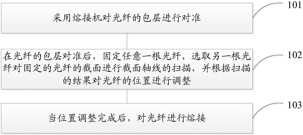
[0076] refer to figure 1 , which shows a flow chart of the steps of an embodiment of an optical fiber fusion splicing method of the present application, which may specifically include the following steps:

[0077] Step 101, using a fusion splicer to align the cladding of the optical fiber;

[0078] Step 102, after the cladding of the optical fiber is aligned, ...


PUM


Abstract

In an embodiment, the application provides a fiber welding method, comprising the steps of: employing a welding machine to align fiber claddings; after aligning the fiber claddings, fixing any fiber, selecting another fiber to scan the cross section axis of the cross section of the fixed fiber, and adjusting a fiber position according to scanning results; and welding the fiber after position adjustment. The method realizes fiber core alignment by scanning fiber end faces, reduces high-order mode generation opportunities, and reduces the influence caused by fiber different batches.

Description

technical field [0001] The present application relates to the field of optical fiber technology, in particular to an optical fiber fusion splicing method and an optical fiber fusion splicing device. Background technique [0002] With the development of laser technology, material processing has entered the era of laser processing, in which fiber lasers have won extensive market attention for their superior beam quality and large output optical power. In fiber lasers, high-power lasers place extremely high requirements on the quality of fiber fusion points. Core mismatch or other flaws at the fiber splice will cause local heating, and even cause the splice to burn out or damage the optical components in the fiber laser system due to light reflection. [0003] The current heating methods used in optical fiber fusion splicing equipment are: electrode discharge heating, graphite burner heating, and carbon dioxide laser heating. The alignment methods are: core alignment and cladd...

Claims


Application Information

Patent Timeline
Patent Type & Authority Applications(China)
IPC IPC(8): G02B6/255
CPCG02B6/2555
Inventor 居剑郭水涛蒋峰
Owner 武汉创鑫激光科技有限公司
Why Eureka
Try Eureka