
PTZ control method and device

A control method and technology of a control device, applied in the field of pan/tilt, can solve problems such as poor self-stabilization effect and inaccurate pan/tilt control, achieve the effect of isolating body disturbance and ensuring imaging quality

Active Publication Date: 2018-05-04
SICHUAN AEE AVIATION TECH CO LTD
View PDF6 Cites 0 Cited by
  • Summary
  • Abstract
  • Description
  • Claims
  • Application Information

AI Technical Summary

Problems solved by technology

[0006] The main purpose of the present invention is to provide a pan-tilt control method and device, aiming to solve the technical problems of inaccurate pan-tilt control and poor self-stabilization effect

Method used


Image

  • PTZ control method and device
  • PTZ control method and device
  • PTZ control method and device

Examples


Embodiment Construction

[0060] It should be understood that the specific embodiments described here are only used to explain the present invention, not to limit the present invention.

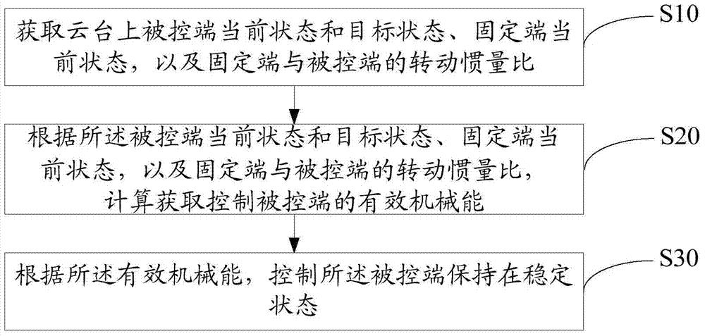
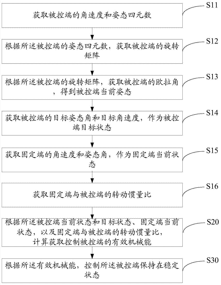
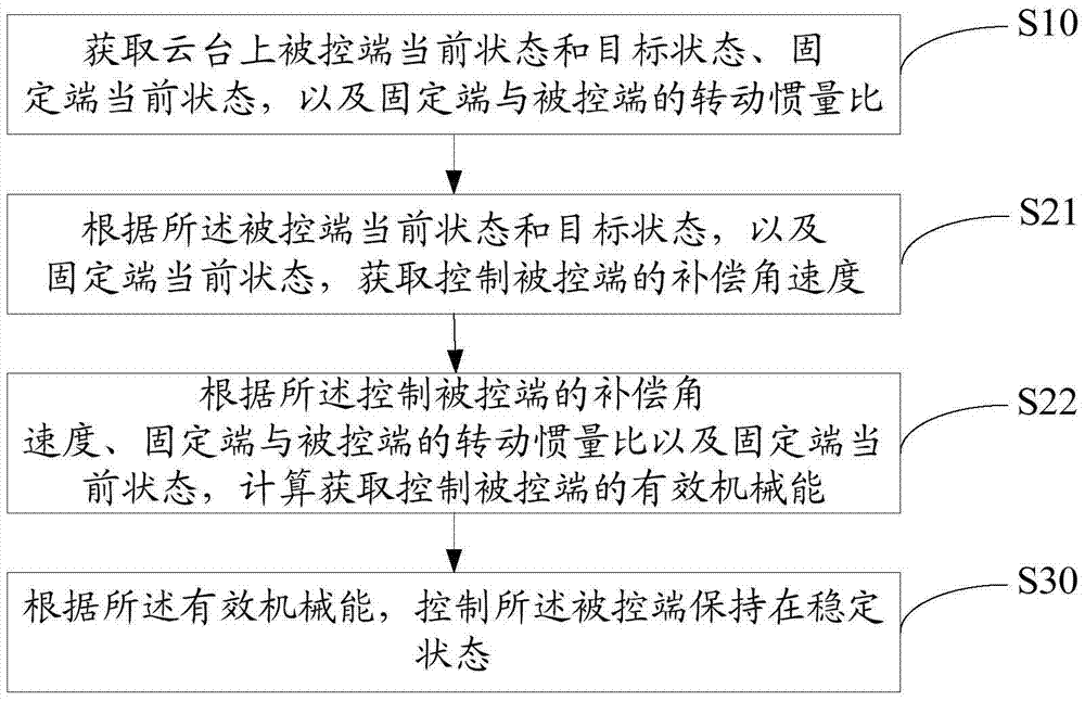
[0061] The main solution of the embodiment of the present invention is: obtain the current state and target state of the controlled terminal on the pan / tilt, the current state of the fixed terminal, and the moment of inertia ratio between the fixed terminal and the controlled terminal; , the current state of the fixed end, and the moment of inertia ratio between the fixed end and the controlled end, calculate and obtain the effective mechanical energy for controlling the controlled end; according to the effective mechanical energy, control the controlled end to maintain a stable state.

[0062]Due to the poor control accuracy of the gimbal in the prior art, it is impossible to accurately adjust the camera attitude to achieve the target attitude, and it cannot effectively isolate the disturbance generated by the body, a...


PUM


Abstract

The invention discloses a cloud platform control method, which obtains the current posture and target posture of the controlled terminal on the platform, the current posture of the fixed terminal, and the moment of inertia ratio between the fixed terminal and the controlled terminal; according to the current posture of the controlled terminal and the target The posture, the current posture of the fixed end, and the moment of inertia ratio between the fixed end and the controlled end are calculated to obtain the effective mechanical energy for controlling the controlled end; according to the effective mechanical energy, the controlled end is controlled to maintain a stable state. The invention also discloses a pan-tilt control device. The invention enables the controlled terminal to reach the target posture and keep it in a stable state, realizes the precise control of the pan-tilt, effectively isolates the disturbance of the body, achieves the self-stabilizing control effect of the pan-tilt, and guarantees the imaging quality of the pan-tilt load camera.

Description

technical field [0001] The invention relates to the field of cloud platform technology, in particular to a method and device for controlling the platform. Background technique [0002] The gimbal is a supporting device for installing and fixing the camera. The three-axis gimbal can control the camera to perform three-axis movements of pitch, roll, and heading, and has high flexibility. [0003] The three-axis gimbal is fixed on the UAV, and as the carrier of the airborne camera, it can be used to isolate disturbances and ensure the stability of the boresight of the UAV airborne camera. Ideally, during the shooting process of the camera, the UAV is always flying horizontally and at a constant speed, and the attitude of the UAV must be kept stable. The three-axis gimbal controls the camera to reach the target attitude, so that the boresight of the airborne camera can be Scans the floor evenly, resulting in high-quality, distortion-free images. [0004] However, there are man...

Claims


Application Information

Patent Timeline
Patent Type & Authority Patents(China)
IPC IPC(8): G05D3/12
Inventor 张显志
Owner SICHUAN AEE AVIATION TECH CO LTD
Learn More