
A microstrip antenna and communication device

A microstrip antenna and transmission line technology, applied in the directions of antennas, antenna supports/installation devices, electrical components, etc., can solve the problem of reducing the cross-polarization suppression ratio of the antenna, improve the cross-polarization suppression ratio, reduce the influence, The effect of improving polarization purity

Active Publication Date: 2019-01-18
HUAWEI TECH CO LTD
View PDF5 Cites 0 Cited by
  • Summary
  • Abstract
  • Description
  • Claims
  • Application Information

AI Technical Summary

Problems solved by technology

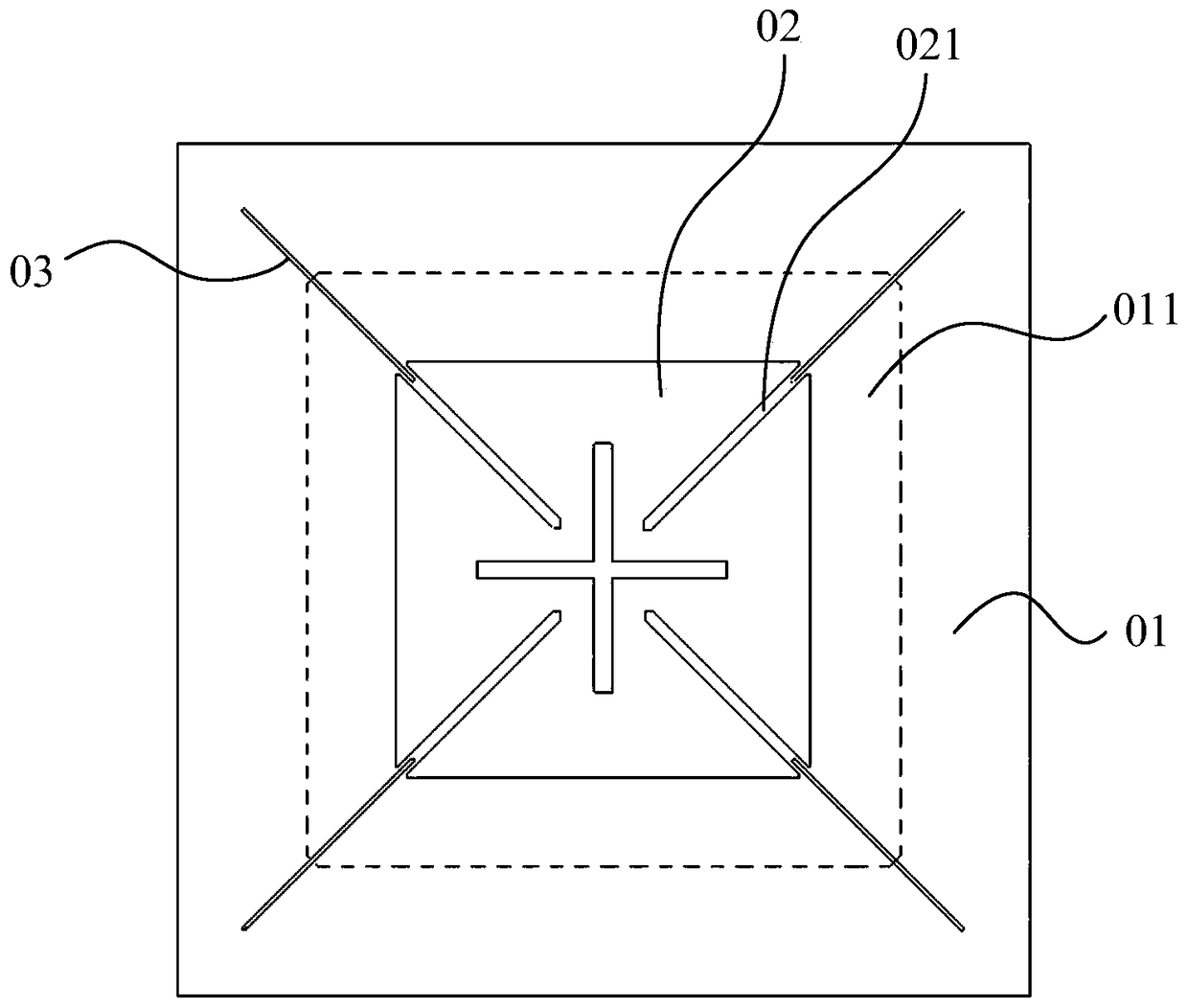
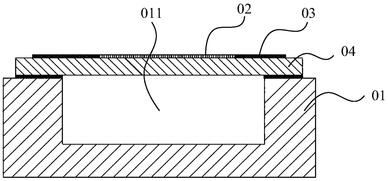
[0004] However, since the above-mentioned cavity-backed antennas are formed into an array, the radiation environment of each side wall of the cavity-back body 01 cannot be completely consistent, so that the horizontal current of the two side walls of the cavity-back body 04 corresponding to one feeding slot 021 The vector synthesis direction of the antenna is not in the main polarization direction, which reduces the cross-polarization rejection ratio of the antenna

Method used


Image

  • A microstrip antenna and communication device
  • A microstrip antenna and communication device
  • A microstrip antenna and communication device

Examples


Embodiment Construction

[0027] The following will clearly and completely describe the technical solutions in the embodiments of the present invention with reference to the accompanying drawings in the embodiments of the present invention. Obviously, the described embodiments are only some, not all, embodiments of the present invention. Based on the embodiments of the present invention, all other embodiments obtained by persons of ordinary skill in the art without making creative efforts belong to the protection scope of the present invention.

[0028] In describing the present invention, it is to be understood that the terms "center", "upper", "lower", "front", "rear", "left", "right", "vertical", "horizontal", The orientations or positional relationships indicated by "top", "bottom", "inner", "outer", etc. are based on the orientations or positional relationships shown in the drawings, and are only for the convenience of describing the present invention and simplifying the description, rather than in...


PUM


Abstract

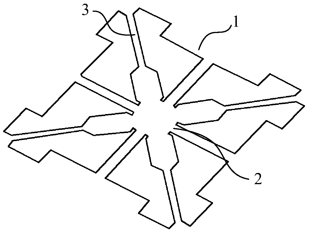
The invention discloses a radiating patch, a microstrip antenna and a communication device and belongs to the antenna technical field. The objective of the invention is to solve the problem of undesirable cross rejection ratio of an existing radiating patch. The radiating patch of the invention is used for a dual-polarized microstrip antenna; the radiating patch is in the shape of a centrally-symmetric figure; a cross-shaped groove is formed in the radiating patch; the cross point of the cross-shaped groove is overlapped with the symmetry center of the radiating patch; the radiating patch is segmented into four radiating units through the cross-shaped groove, wherein the four radiating units are isolated from each other; a feed groove is formed in each radiating unit; the included angle between the center line of the feed groove and the center line of the cross-shaped groove is 45 degrees; the extension direction of the center line of the feed groove is consistent with a polarization direction where the radiating unit is located, the feed groove being located at the radiating unit; the feed groove is of an open structure; and the opening of the feed groove is located at the external side of the radiating unit and faces the exterior of the radiating unit. The radiating patch of the invention can be applied to the design of mobile communication base station antennas.

Description

technical field [0001] The invention relates to the technical field of antennas, in particular to a microstrip antenna and a communication device. Background technique [0002] With the development of antenna technology, there are more and more ways to implement microstrip antennas, including cavity-backed antennas, dipole antennas, loop antennas, slot antennas, aperture antennas, and end-fire antennas. It can improve the radiation performance of the antenna, and has been extensively studied. [0003] Existing cavity-backed antennas include a radiation unit, a cavity-backed body and a feeding structure, wherein the cavity-backed body is usually composed of a smooth metal cavity. figure 1 and figure 2 Shown is an existing cavity-backed antenna, which includes a cavity-back main body 01, a radiation patch 02, a transmission line 03, and a top plate 04. The upper surface of the cavity-back main body 01 is provided with a square back cavity 011, and the shape of the radiation...

Claims


Application Information

Patent Timeline
Patent Type & Authority Patents(China)
IPC IPC(8): H01Q1/38H01Q13/08H01Q1/24
Inventor 罗兵石中立覃雯斐
Owner HUAWEI TECH CO LTD
Learn More