Precise GNSS directional antenna

A positioning antenna, precision technology, applied in the direction of antenna, antenna support/mounting device, electrical components, etc., can solve the requirements of high dimensional accuracy and helix forming of four-armed helical antenna, the helical arm of the antenna cannot realize the standing wave distribution, The four-arm helical antenna has narrow working bandwidth and other problems, so as to achieve the effect of increasing frequency coverage, beautiful appearance and simple processing.

Active Publication Date: 2013-05-01
SPACE STAR TECH CO LTD
View PDF6 Cites 1 Cited by
  • Summary
  • Abstract
  • Description
  • Claims
  • Application Information

AI Technical Summary

Problems solved by technology

like figure 1 As shown, a typical quadrifilar helical antenna is mainly composed of a helical arm and a feed support structure. The advantages of this antenna are small electrical size, compact structure, high radiation efficiency, good wide-angle beam gain coverage and relatively high High front-to-back ratio, but because the four-arm helical antenna is a resonant antenna, the resonance is mainly achieved by adjusting the length of the helical arm, so that the current on the helical arm presents a standing wave distribution, which results in a narrower working bandwidth of the four-arm helical antenna. The frequency range of GPS, BD-2, GALILEO and GLONASS cannot be fully covered, and due to the limitation of the length of the helical arm, the current distribution of the helical arm at each operating frequency point is inconsistent, and the current of the antenna helical arm cannot achieve standing waves at some operating frequency points distribution, which deteriorates the radiation pattern of the antenna, and at the same time leads to poor stability of its phase center in the wide-band and wide-beam range, thus affecting the overall performance of the antenna
The four-arm helical antenna has high requirements for dimensional accuracy and helix forming, the structure and processing technology are complicated, and the cost is high

Method used


Image

  • Precise GNSS directional antenna
  • Precise GNSS directional antenna
  • Precise GNSS directional antenna

Examples


Embodiment Construction

[0030] Specific embodiments of the present invention will be further described in detail below in conjunction with the accompanying drawings.

[0031] In order to meet the increasing demand for satellite positioning accuracy of users, the Global Navigation Satellite System (GNSS, Global NaVigation Satellite System) that accommodates all current navigation satellite systems has been proposed internationally. This system includes GPS (Global Positioning System, American Navigation Satellite System), BD-2 (Beidou, China Navigation Satellite System), GALILEO (European Navigation Satellite System) and GLONASS (Russian Navigation Satellite System), compared with the existing GPS navigation satellite system, GNSS can provide higher-precision positioning information, clocks, etc. . Antenna is a key component of a high-precision positioning system, and high-precision positioning antenna technology has become an urgent problem to be solved.

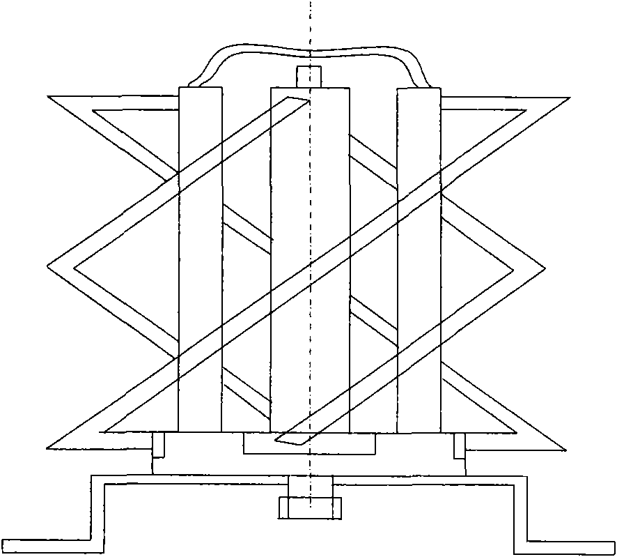
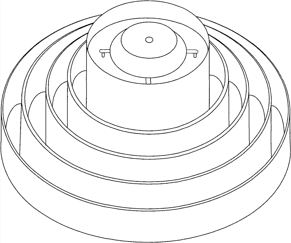
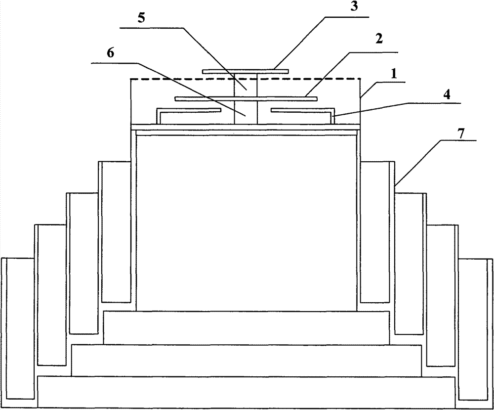
[0032] combine figure 2 and image 3 , t...


PUM


Abstract

A precise GNSS directional antenna includes a reflection cavity, a radiation lower patch, a radiation upper patch, four L-shaped metal feed probes, a first supporting column, a second supporting column and a choke groove. The reflection cavity is a hollow cylinder of which a bottom surface is closed, height of the reflection cavity is a little bit lower than the radiation upper patch and higher than the radiation lower patch, the radiation lower patch is higher than the L-shaped metal feed probes and concentrically connected with an inner bottom surface of the reflection cavity by the second supporting column, and the radiation upper patch is concentrically connected with the radiation lower patch by the first supporting column. The four L-shaped metal feed probes are installed on an inner bottom surface of a transmitting cavity and uniformly distributed on same circle. The bottom surface of the reflection cavity is installed on the choke groove, the choke groove is a pyramidal structure, height of four choke rings decreases progressively from the inside to the outside, and each choke ring has equal depth and equal interval. The precise GNSS directional antenna has wider beam coverage capability and strong multi-path interference resistance in low elevation direction, and is suitable for a precise positioning system.

Description

technical field [0001] The invention relates to an antenna, in particular to a precision GNSS positioning antenna, and belongs to the technical field of high-precision positioning antennas. Background technique [0002] With the improvement of users' demand for satellite positioning accuracy, the positioning accuracy of the existing GPS satellite positioning system can no longer meet the needs of users for high-precision positioning. Navigation Satellite System), as a key component in the satellite positioning system, high-precision positioning antenna technology has become an urgent problem to be solved. [0003] Satellite positioning antenna is a wide-beam antenna, which requires the antenna to have high gain and stable phase center in the wide-angle range, and to have a certain ability to resist multipath interference in the direction of low elevation angle. At present, the satellite positioning antenna mostly adopts the form of a four-arm helical antenna and a choke rin...

Claims


Application Information

Patent Timeline
Patent Type & Authority Patents(China)
IPC IPC(8): H01Q1/12H01Q1/36H01Q19/17
Inventor 刘宁民李时良张胜辉李景贵郭文嘉
Owner SPACE STAR TECH CO LTD
Why Eureka
Try Eureka