Eureka AIR delivers breakthrough ideas for toughest innovation challenges, trusted by R&D personnel around the world.

Dynamic distributed antenna deployment method for enhancing network capacity and coverage

A distributed antenna and network enhancement technology, applied in the field of dynamic distributed antenna deployment, can solve problems such as inability to adapt to network dynamic changes, and achieve the effects of improving received signal strength, increasing network capacity, and solving limited capacity.

Active Publication Date: 2015-12-02
CHONGQING UNIV OF POSTS & TELECOMM
View PDF5 Cites 12 Cited by
  • Summary
  • Abstract
  • Description
  • Claims
  • Application Information

AI Technical Summary

Problems solved by technology

This distributed antenna deployment strategy cannot adapt to the dynamic changes of the network, and cannot provide sufficient flexible resource allocation during periods of high network service demand.

Method used


Image

  • Dynamic distributed antenna deployment method for enhancing network capacity and coverage
  • Dynamic distributed antenna deployment method for enhancing network capacity and coverage
  • Dynamic distributed antenna deployment method for enhancing network capacity and coverage

Examples


Embodiment Construction

[0032] The preferred embodiments of the present invention will be described in detail below with reference to the accompanying drawings.

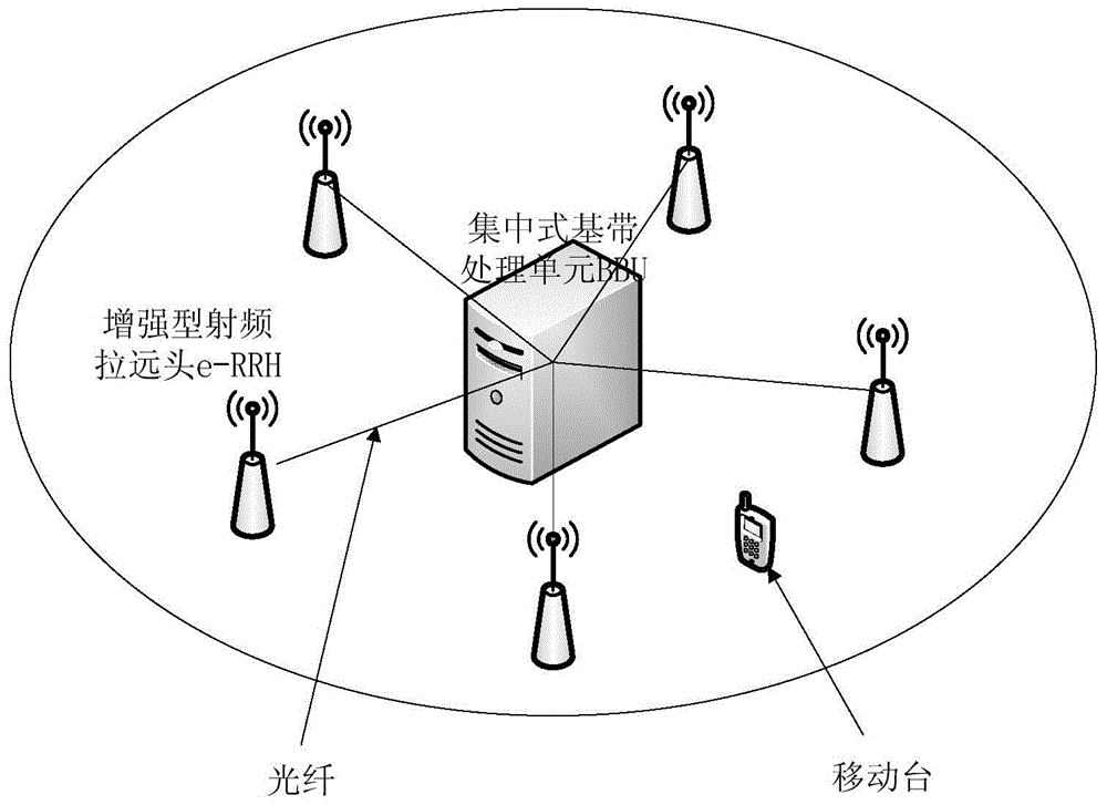
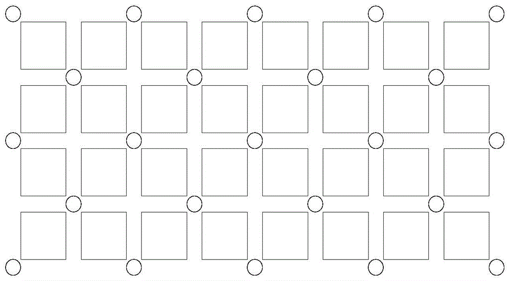
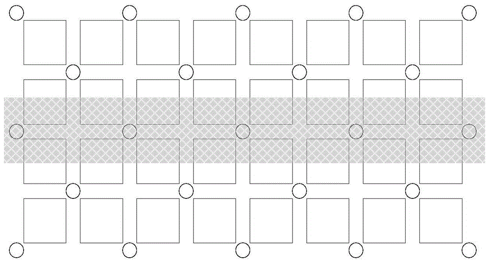
[0033] Figure 10It is a schematic flow chart of the method of the present invention. As shown in the figure, the method includes the following steps: 1) Aiming at the current urban planning status of buildings and streets in the actual network, deploying at traffic light intersections in cross streets under the urban network environment Distributed antenna remote radio head RRH module. These remote radio heads are connected to the baseband processing unit BBU module through the backhaul link. The remote radio heads in different positions can be clustered to form different networks according to network requirements during network planning. Distributed antenna cells in geographical form; 2) There is a central cluster head site among all network nodes clustered into a distributed antenna cell, and the centralized processing server module need...


PUM


Abstract

The invention relates to a dynamic distributed antenna deployment method for enhancing the network capacity and coverage. The method comprises the following steps: deploying distributed antenna nodes on crossroads in a city network, wherein remote radio head nodes of distributed antennas can be clustered into distributed antenna cells of different forms in different ways; and when loads in the clustered cells are light, executing a radio frequency receiving-transmitting functional module of a remote radio head to transmit the same data under the configuration of a central processing server module in a center cluster head station of the clustered cells through network nodes in the same distributed antenna cell in order to enhance signal receiving intensity of users within a service range. Compared with a method for separately deploying hot-spot base stations, the dynamic distributed antenna deployment method has the advantages that the influence of interference between adjacent base stations under dense network deployment can be lowered, and the mobility problems of excessive switching times, high switching failure rate and the like due to dense deployment under the situation of a narrowed cell range are solved.

Description

technical field [0001] The invention belongs to the technical field of wireless communication, and relates to a dynamic distributed antenna deployment method for enhancing network capacity and coverage. Background technique [0002] With the full commercialization of 4G standard networks, the mobile Internet has entered an era of rapid development, and its requirements for the capacity of future wireless communication networks are getting higher and higher. In order to meet the business needs of users and ensure the continuous wide-area coverage of the network, in the LTE heterogeneous cellular network, on the basis of the basic network coverage provided by the traditional macro base station, small cells are deployed in hotspot areas to meet the business needs of hotspots. and capacity requirements. In the next-generation wireless communication network, the deployment of ultra-dense heterogeneous networks has been recognized as an extremely important aspect to improve netwo...

Claims


Application Information

Patent Timeline
Patent Type & Authority Applications(China)
IPC IPC(8): H04W16/18H04W16/26H04B7/26
CPCH04B7/2609H04W16/18H04W16/26
Inventor 唐伦刘伟郝昊黄鹏陈前斌
Owner CHONGQING UNIV OF POSTS & TELECOMM
Why Eureka
Eureka Blog
Learn More