
Measuring system and measuring method for thermal deformation of components in vacuum environment

A measurement system and vacuum environment technology, applied in the direction of electric/magnetic solid deformation measurement, measurement devices, electromagnetic measurement devices, etc., can solve the problems of hidden dangers affecting product performance, lack of verification means, etc., to eliminate hidden dangers of deformation, high detection accuracy, The effect of improving measurement accuracy

Active Publication Date: 2013-01-02
SHANGHAI SATELLITE ENG INST
View PDF0 Cites 14 Cited by
  • Summary
  • Abstract
  • Description
  • Claims
  • Application Information

AI Technical Summary

Problems solved by technology

[0005] In order to solve the lack of verification means for the results of design and simulation calculations in the prior art, resulting in problems such as hidden dangers affecting product performance, the first aspect of the purpose of the present invention is to provide a thermal deformation measurement system for components in a vacuum environment
The invention can solve the detection problem of the thermal deformation performance of the components on the star under the environment of the vacuum temperature field

Method used


Image

  • Measuring system and measuring method for thermal deformation of components in vacuum environment

Examples


Embodiment Construction

[0023] The preferred embodiment of the first aspect of the present invention will be described below with reference to the accompanying drawings.

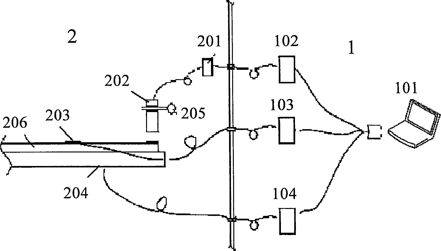
[0024] The accompanying drawing is the first aspect of the present invention, a structural schematic diagram of a component thermal deformation measurement system in a vacuum environment, as shown in the embodiment of the accompanying drawing, the device includes: a testing system 1 (right side in the figure) and a vacuum test tank 2 (left side in the picture).

[0025] The above-mentioned testing system 1 includes: a computer 101 is connected to the displacement measurement system 102, the temperature measurement system 103, and the heating system 104 through cables to control the actions of these systems and process the test data of these systems.

[0026] The above-mentioned vacuum test tank 2 has an infrared heating cage forming a temperature field; various test devices are installed in the vacuum test tank 2, including:

[00...


PUM


Abstract

The present invention relates to component thermal deformation measurement, and discloses a component thermal deformation measurement system in a vacuum environment, including a test system [1] and a vacuum test tank [2]; the test system [1] includes: a computer [101] and The displacement measurement system [102], the temperature measurement system [103] and the heating system [104] are connected to control the actions of these systems and process the test data of these systems. In the vacuum test tank [2], the measured component [206] is installed on the carbon fiber reference frame [205], and a thermal control multi-layer composed of a thermocouple [203] and a heating plate [204]; the measured component [206] The characteristic parts are equipped with eddy current displacement sensors [202]. The invention also discloses the measuring method of the system. The invention solves the problem of verifying whether the design and simulation analysis calculation are correct, and achieves beneficial effects such as simple operation, high detection precision, and low equipment cost.

Description

technical field [0001] The invention relates to component thermal deformation measurement, in particular to a measurement system for generating thermal deformation conditions of aircraft components for a temperature field formed in a space vacuum environment, and also relates to a measurement method of the measurement system. Background technique [0002] When the aircraft is working in orbit, the harsh vacuum and temperature environment in space often cause deformation of components such as SAR antennas, which adversely affects its performance. Therefore, product design and ground detection of thermal deformation in a vacuum environment have always been one of the technical difficulties that have been concerned. [0003] Before the application of the present invention, the thermal deformation of aerospace products is mainly analyzed through the results of design and simulation calculations. Due to the lack of verification means for the results of such design and simulation ...

Claims


Application Information

Patent Timeline
Patent Type & Authority Patents(China)
IPC IPC(8): G01B7/16G01N25/00
Inventor 顾志悦张红英蓝增瑞
Owner SHANGHAI SATELLITE ENG INST
Learn More