mist generating device

A technology for generating devices and mist, which is applied in bathing devices, physical therapy, etc., and can solve problems such as non-reaching

Active Publication Date: 2017-09-22
PANASONIC INTELLECTUAL PROPERTY MANAGEMENT CO LTD
View PDF1 Cites 0 Cited by
  • Summary
  • Abstract
  • Description
  • Claims
  • Application Information

AI Technical Summary

Problems solved by technology

With such a mist generating device, the flow of the warm mist and the flow of the cool mist are different from each other as described above, and therefore, there is a possibility that one or both of the warm mist and the cool mist do not reach their respective target arrival positions.

Method used


Image

  • mist generating device
  • mist generating device
  • mist generating device

Examples


Embodiment approach 1

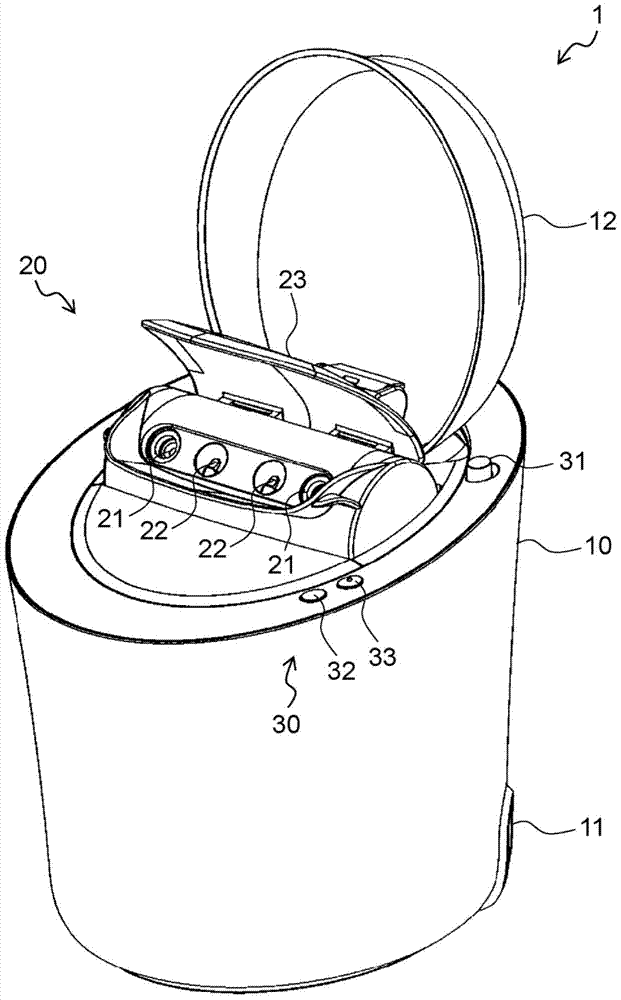
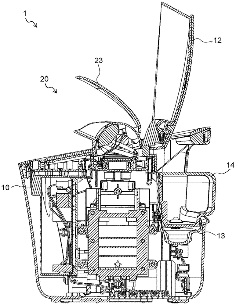
[0033] refer to figure 1 with figure 2 , the structure of the mist generating device 1 will be described.

[0034] figure 1 It is a perspective view of the mist generator 1 in Embodiment 1 of this invention. Such as figure 1 As shown, the mist-generating device 1 has a housing 10 constituting the outer shell. The mist generating device 1 receives power supplied from a power source from the outside through a power connector 11 formed under the housing 10 .

[0035] The shape of the case 10 is substantially cylindrical in this embodiment. A nozzle portion 20 for spraying mist and an operation switch 30 for operating the mist generator 1 are formed on the upper surface of the housing 10 . In addition, a main body cover 12 that can be opened and closed so as to expose or hide the nozzle portion 20 is formed on the casing 10 .

[0036] The nozzle portion 20 is formed at a central portion of the upper surface of the housing 10 . The nozzle part 20 has at least one warm mist...

Embodiment approach 2

[0083] The mist generator 2 of Embodiment 2 of the present invention has a structure different from that of the mist generator 1 of Embodiment 1 in the aspects described below, and the mist generator 2 of Embodiment 2 has the same structure as that of Embodiment 1 in other respects. The mist generating device 1 has substantially the same structure. In addition, in the description of the mist generator 2 of Embodiment 2, the same reference numerals are assigned to the configurations common to the mist generator 1 of Embodiment 1, and a part or all of the descriptions of the configurations are omitted.

[0084] refer to Figure 10 , and the structure of the mist generator 2 of this embodiment will be described.

[0085] Figure 10 It is a perspective view of the mist generator 2 in Embodiment 2 of this invention.

[0086] The mist generator 2 of the present embodiment has a case 10 constituting an outer shell. The mist generating device 2 is formed on the power connector 11 ...


PUM


Abstract

The mist generating device has a warm mist generating part (40) for generating warm mist, a cool mist generating part (50) for generating cool mist, warm mist outlets (21, 21A) for spraying warm mist, and In the cool mist outlet (22) of spraying cool mist. Considering the flow characteristics of warm mist and cool mist, in order to make the warm mist and cool mist reach their respective target arrival positions, the mist generating device is set so that the orientation of the warm mist outlet and the direction of the cool mist outlet are opposite to each other. not in the same direction.

Description

technical field [0001] The present invention relates to a mist generating device for generating warm mist and cool mist. Background technique [0002] There is known a kind of mist generating device which can spray warm mist and cool mist. Feel the cool temperature. An example of a mist generator is disclosed in patent document 1 (Japanese Unexamined Patent Application Publication No. 2010-187765). The mist generating device provides, for example, an effect of promoting beauty to the skin by supplying warm mist and cool mist to the user's skin. [0003] Patent Document 1 does not particularly describe the flow characteristics of warm mist and cool mist. Generally, the warm mist has the characteristic of flowing upward as the flight distance becomes longer, and the cool mist has the characteristic of flowing downward as the flight distance becomes longer. [0004] In addition, Patent Document 1 discloses that the direction of the warm mist nozzle and the direction of the ...

Claims


Application Information

Patent Timeline
Patent Type & Authority Patents(China)
IPC IPC(8): A61H33/12
Inventor 北村央大野木洋子
Owner PANASONIC INTELLECTUAL PROPERTY MANAGEMENT CO LTD
Why Eureka
Try Eureka