Solar heat collector, solar heat collecting multilayer sheet, and solar heat heater
A solar heat collection and multi-layer technology, which is applied in the directions of solar collectors, solar collector shells, and components of solar collectors, etc., can solve problems such as inability to conduct heat and heat.
- Summary
- Abstract
- Description
- Claims
- Application Information
AI Technical Summary
Problems solved by technology
Method used
Image
Examples
no. 1 Embodiment approach
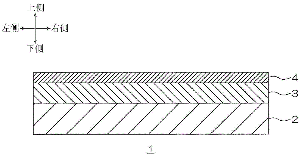
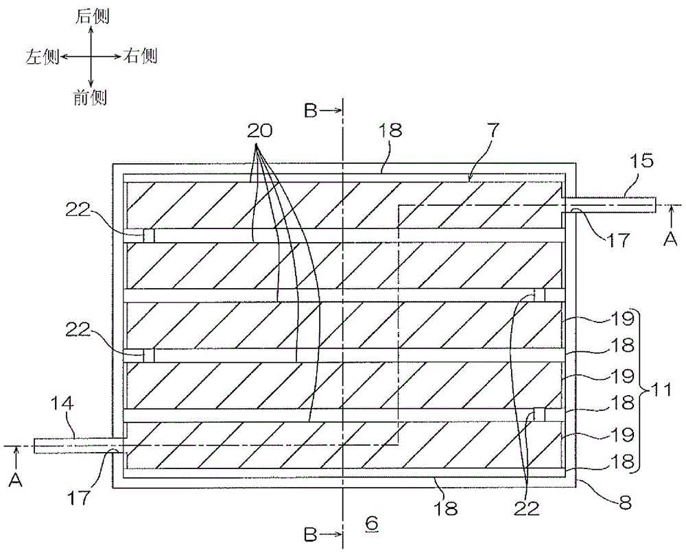
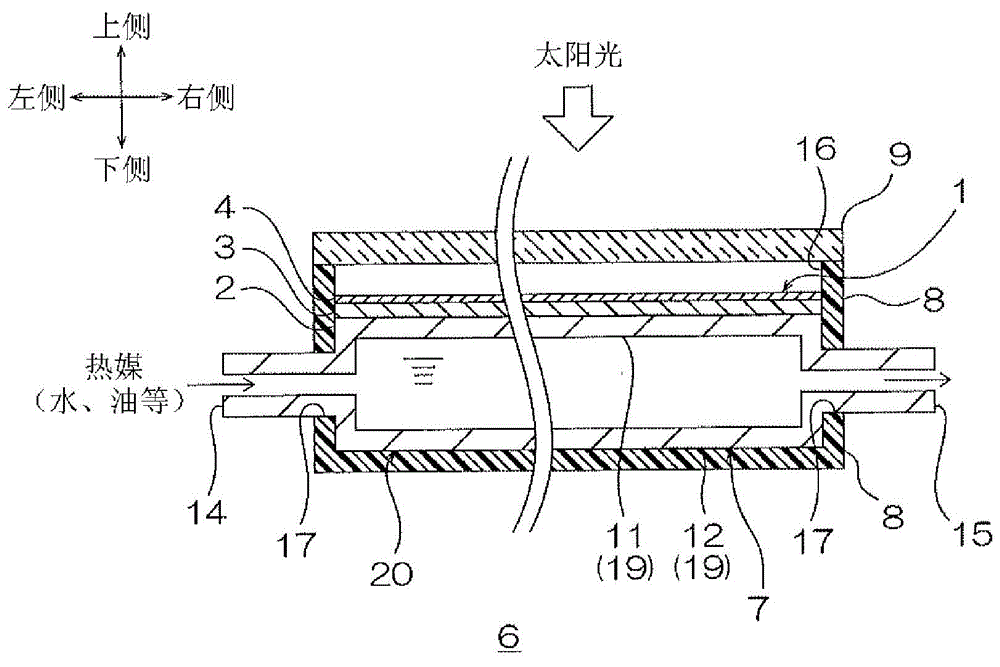
[0037] exist figure 1 In the above, the upper side of the paper indicates the upper side (one side in the first direction, one side in the thickness direction), the lower side in the paper indicates the lower side (the other side in the first direction, and the other side in the thickness direction), and the left side in the paper indicates the left side. side (the side of the second direction orthogonal to the first direction), the right side of the paper indicates the right side (the other side of the second direction), and the near side of the paper indicates the front side (orthogonal to the first direction and the second direction). One side of the third direction), and the depth side of the paper indicates the rear side (the other side of the third direction). Specifically, the direction is figure 1 The direction arrow of . figure 2 Subsequent figures start with figure 1 direction as the basis. In addition, in figure 2 In the figure, in order to clearly show the r...
no. 2 Embodiment approach
[0081] In the second embodiment, the same reference numerals are assigned to the same components and steps as those in the first embodiment, and detailed description thereof will be omitted.
[0082] Such as Figure 5 As shown, the solar heat collection multilayer sheet 21 has a substrate sheet 10 , a solar radiation absorbing layer 3 and a low emissivity-low solar reflectance layer 4 .
[0083] The substrate sheet 10 is used to support the solar radiation absorbing layer 3 and the low emissivity-low solar reflectance layer 4, and the solar radiation absorbing layer 3 and the low emissivity-low solar reflectance layer 4 are arranged on the heat collecting plate 2 (imaginary line) support sheet. The plan view shape of the base material sheet 10 is formed to be the same as the plan view shape of the solar heat collecting multilayer sheet 21 . In addition, the external shape of the base material sheet 10 is not limited to the said shape, It can be formed in an appropriate shape...
Embodiment 1
[0107] Make solar collectors
[0108]Prepare an aluminum plate (thickness 0.5mm) as a heat collecting plate, then apply a black body paint on the upper surface of the heat collecting plate to form a sunlight absorbing layer (thickness 30 μm), then, on the upper surface of the sunlight absorbing layer, use An ITO film (thickness 250nm) was formed as a low emissivity-low solar reflectance layer by sputtering. Thus, a solar thermal collector including a heat collecting plate, a solar absorbing layer and a low emissivity-low solar reflectance layer (refer to figure 1 ).
PUM
| Property | Measurement | Unit |
|---|---|---|
| thickness | aaaaa | aaaaa |
| thickness | aaaaa | aaaaa |
| thickness | aaaaa | aaaaa |
Abstract
Description
Claims
Application Information
 - R&D
- Intellectual Property
- Life Sciences
- Materials
- Tech Scout
- Unparalleled Data Quality
- Higher Quality Content
- 60% Fewer Hallucinations
Browse by: Latest US Patents, China's latest patents, Technical Efficacy Thesaurus, Application Domain, Technology Topic, Popular Technical Reports.
© 2025 PatSnap. All rights reserved.Legal|Privacy policy|Modern Slavery Act Transparency Statement|Sitemap|About US| Contact US: help@patsnap.com


