Air cooling structure of outer rotor electric roller

A technology of electric drum and air-cooled structure, which is applied in the direction of electric components, magnetic circuit shape/style/structure, electrical components, etc., and can solve the problem of long distance between the shaft hole and the heating part of the motor stator, high equipment manufacturing cost, and slow heat transfer, etc. problem, to achieve the effect of improving heat dissipation, saving manufacturing cost and prolonging service life

Active Publication Date: 2020-05-08
JIANGSU JIAXUAN INTELLIGENT IND TECH CO LTD
View PDF6 Cites 9 Cited by
  • Summary
  • Abstract
  • Description
  • Claims
  • Application Information

AI Technical Summary

Problems solved by technology

[0005] When the above-mentioned cooling structure drum is designed as a water-cooling structure, additional water-cooling equipment is required, and the on-site installation takes up a lot of space. Both the water-cooling equipment and pipe joints need to spend manpower and material resources for regular maintenance, and the manufacturing cost of the equipment itself is also high. At the same time, in the air-cooling technology The small air inlet of the hollow shaft hole leads to small air flow, and the distance between the shaft hole and the heating part of the motor stator is long, the heat transfer is slow, and it is difficult to dissipate heat in time. In addition, the wind resistance flowing into the stator from the shaft radial hole is relatively large, requiring high-pressure air. The installation site is often limited by conditions

Method used


Image

  • Air cooling structure of outer rotor electric roller
  • Air cooling structure of outer rotor electric roller
  • Air cooling structure of outer rotor electric roller

Examples


Embodiment Construction

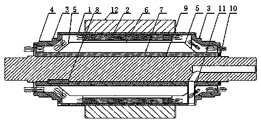
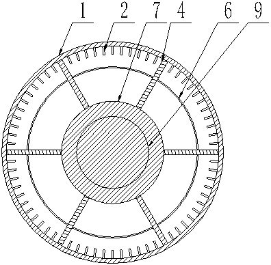
[0032] Below in conjunction with accompanying drawing, describe this description in detail:

[0033] like Figure 1-8 As shown, the present invention includes a fixing seat 27, an end cover assembly, and a stator assembly. The fixed seat 27 includes an intermediate shaft sleeve 26, an axial support rib 22, and a fixed outer ring 24. The end cover assembly includes an end cover 15, an oil cover assembly, a bearing 17, and a sealing device. The stator assembly includes a stator sleeve 1, an axial Rib 4 , wind deflector structure, bearing seat 3 , main shaft 9 , stator coil core assembly 12 . The fixed seat 27 is fixed together through the key connection or shrink fit between the intermediate shaft sleeve 26 and the main shaft 9 , and the stator assembly and the end cover assembly are welded together with the outer ring of the bearing seat 3 through the stator sleeve 1 .

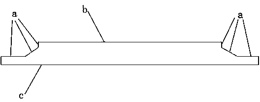
[0034] like Figure 8 As shown, in the preferred embodiment of the air-cooled structure of the outer roto...


PUM


Abstract

The invention discloses an air cooling structure of an outer rotor electric roller. The air cooling structure comprises a fixed seat (27), an end cover assembly and a stator assembly, the stator assembly comprises a stator sleeve (1), an axial rib plate (4), an air deflector structure, a bearing pedestal (3), a main shaft (9) and a stator coil iron core assembly (12). The air deflector structure is connected with the axial rib plate (4) and the main shaft (9); the axial rib plate (4) is connected with the bearing seat (3), the stator sleeve (1) and the main shaft (9); air inlet and outlet ducts are distributed on the fixed seat (27); air inlets and outlets are distributed in the end cover assembly; a ventilating duct is formed outside a shaft among the stator sleeve (1), the air deflectorstructure and the axial rib plate (4); the fan at one end of the main shaft (9) sends cooling air flow into the ventilating duct through a fixing base (27) and the end cover assembly to cool a statoriron core, and then through the ventilating duct outside the shaft, the flow of the cooling air entering the stator is increased, the heat dissipation effect is enhanced, and therefore the service life of the electric roller is effectively prolonged.

Description

technical field [0001] The invention relates to the technical field of electric drive systems, and more specifically relates to an air-cooled structure of an outer rotor electric drum. Background technique [0002] The outer rotor electric drum has the advantages of simple structure, reliable operation, less loss, high efficiency, and can realize direct drive control. It is especially suitable for low-speed, high-torque applications, so it is widely used in petroleum, mining, metallurgy and steel rolling industries. When the outer rotor electric drum is working, the coil installed on the stator will generate a large amount of induction heat, which will easily lead to the aging of the motor and affect the service life of the outer rotor electric drum. In order to improve the heat dissipation capacity of the outer rotor electric drum, a reasonable cooling The system is very necessary to control the temperature rise of the outer rotor electric drum, so the equipment needs to be...

Claims


Application Information

Patent Timeline
Patent Type & Authority Applications(China)
IPC IPC(8): H02K9/04H02K1/20H02K5/16H02K5/173
CPCH02K1/20H02K5/16H02K5/173H02K9/04
Inventor 张春晖李文龙
Owner JIANGSU JIAXUAN INTELLIGENT IND TECH CO LTD
Why Eureka
Try Eureka