Vehicle headlight

A technology for headlights and vehicles, which is applied in the directions of headlights, vehicle parts, lighting devices, etc., to achieve the effect of high position accuracy and simple structure

Inactive Publication Date: 2005-06-08
KOITO MFG CO LTD
View PDF1 Cites 9 Cited by
  • Summary
  • Abstract
  • Description
  • Claims
  • Application Information

AI Technical Summary

Problems solved by technology

[0007] However, there is a problem that in order to realize the above-mentioned solution, the optical axes of each lamp unit must be al

Method used


Image

  • Vehicle headlight
  • Vehicle headlight
  • Vehicle headlight

Examples


Embodiment Construction

[0098] Hereinafter, embodiments of the present invention will be described with reference to the drawings.

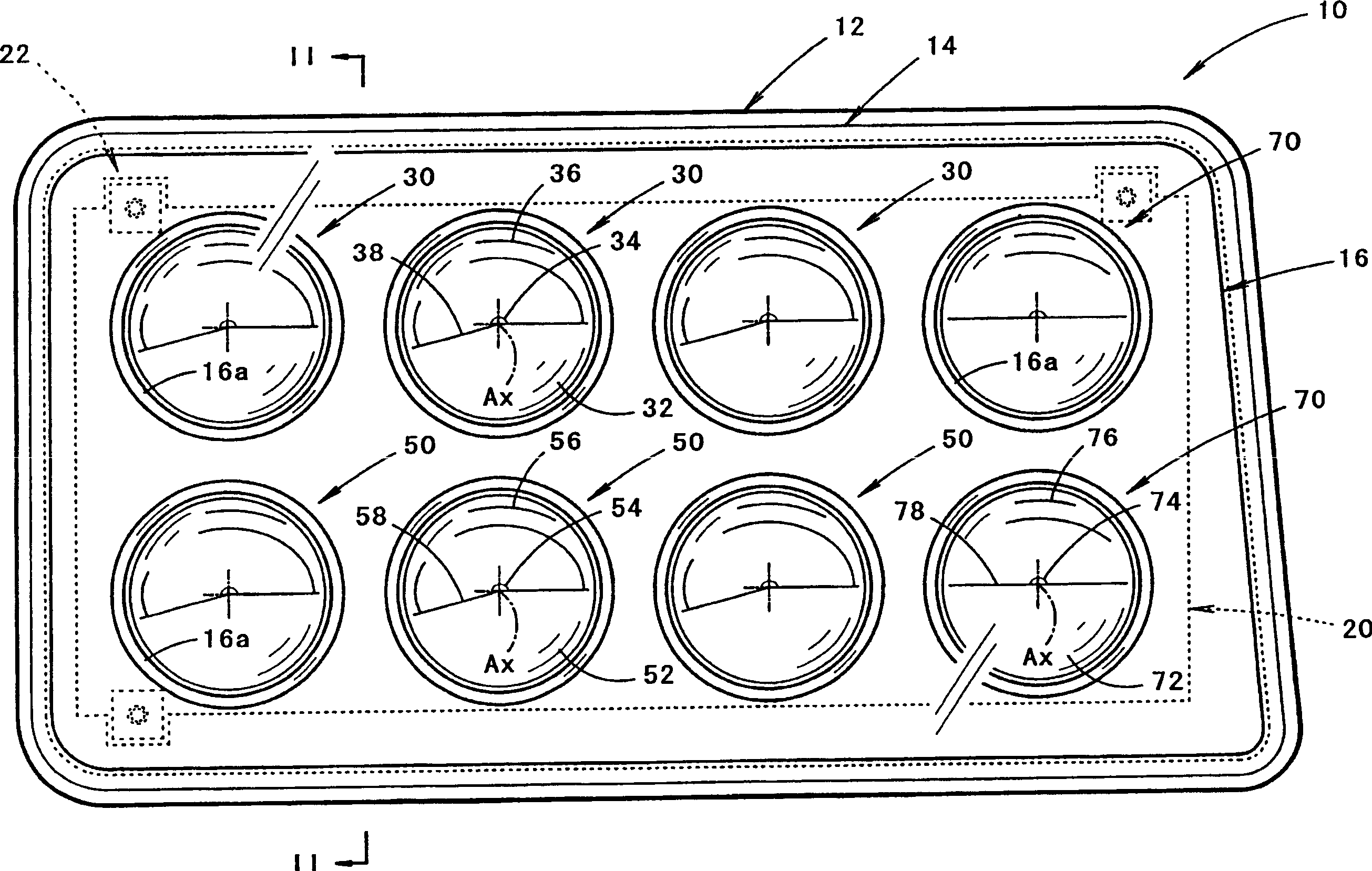
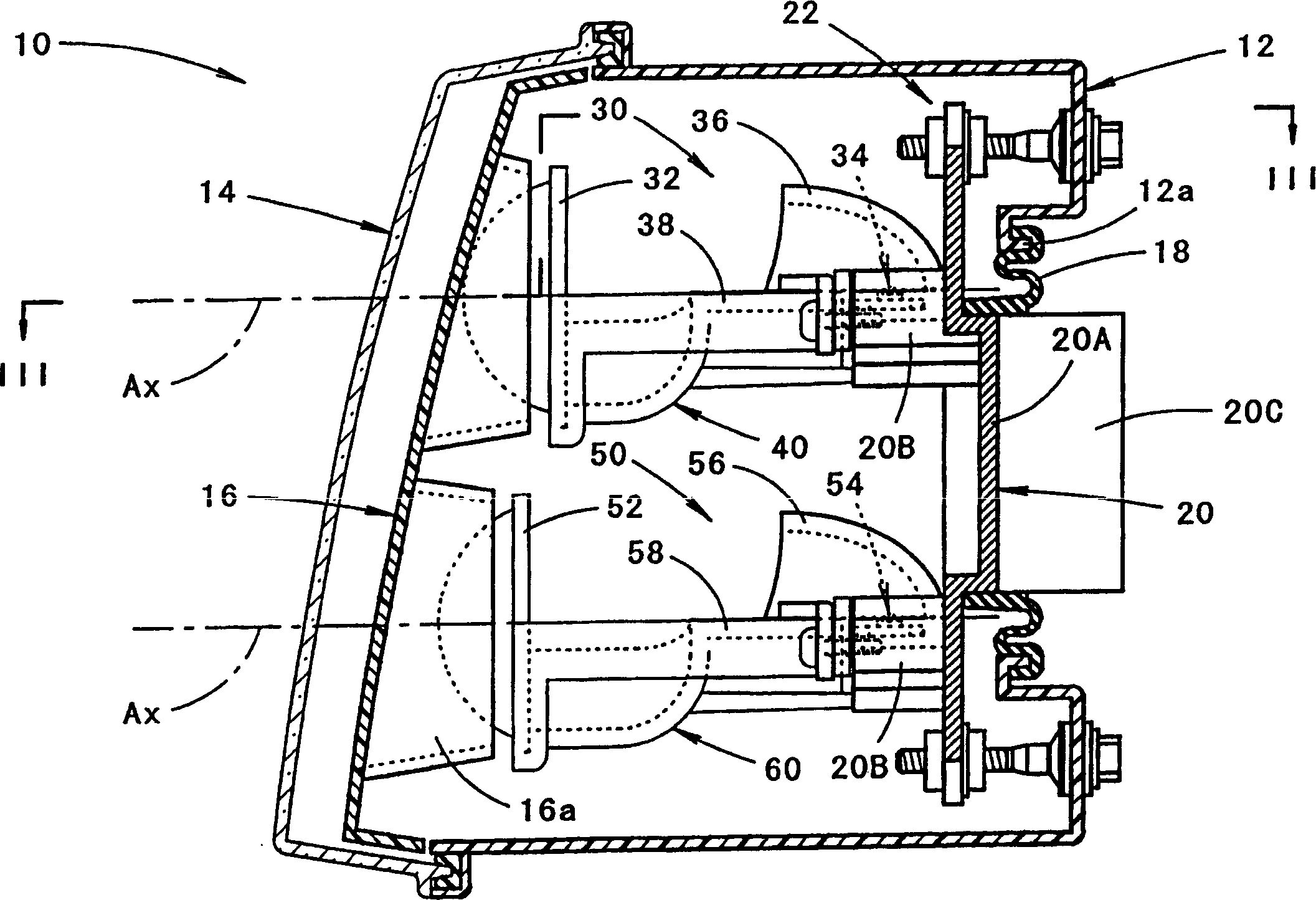
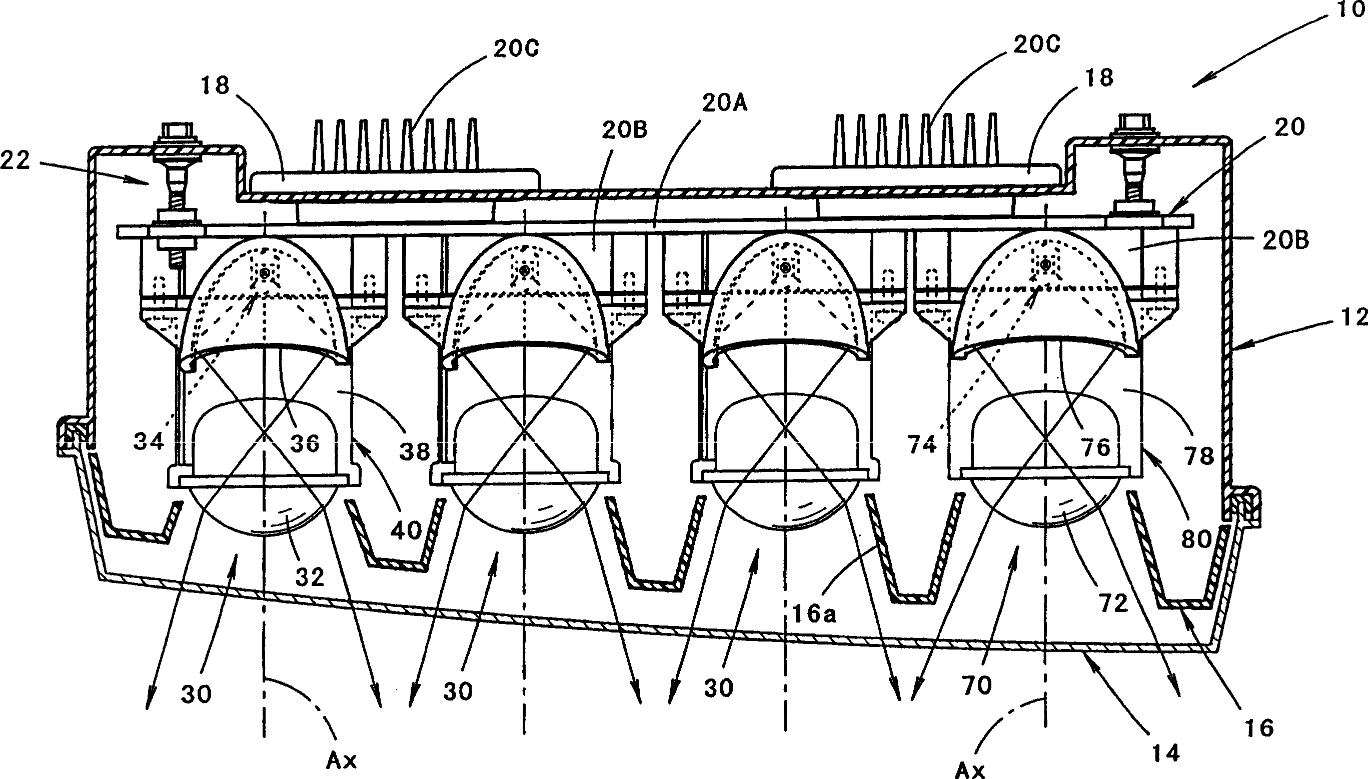
[0099] figure 1 is a front view of a vehicle headlamp according to an embodiment of the present invention, figure 2 yes figure 1 The II-II line profile, image 3 yes figure 2 Sectional view of line III-III.

[0100] As shown in these figures, the vehicle headlamp 10 of this embodiment is a lamp installed on the right side of the front end of the vehicle. Eight lamp units 30, 50, 70 are accommodated, and each floor has two upper and lower floors and each floor has four configurations. In addition, in this vehicle headlamp 10 , light irradiation from these eight lamp units 30 , 50 , and 70 forms a low beam light distribution pattern.

[0101] In the light chamber, an inner panel 16 is provided along the translucent cover 14, and cylindrical openings 16a surrounding each lamp unit are formed at positions corresponding to the lamp units 30, 50, 70 in the inner panel...


PUM


Abstract

Optical axes are simultaneously adjusted when a plurality of lighting device units 30, the light sources of which are light emitting elements 34, are tiltably supported by the common unit support member 20. In this case, the positioning recess portion 20 d is provided which is composed so that the light source fixing portion 20 B 1 formed in a plurality of portions of the unit support member 20 can be contacted with the back face 42 a and the outer circumferential face 42 b of the support plate 42 for supporting the light emitting element 34. Due to the foregoing, the light emitting element 34 can be highly accurately attached to the unit support member 20, and the optical axes Ax, of the lighting device units 30 can be put in order.

Description

technical field [0001] The present invention relates to a vehicle headlamp that forms a predetermined light distribution pattern by light irradiation from a plurality of lamp units. Background technique [0002] Usually, the vehicle headlamp is a structure that can form a low beam light distribution pattern with a cut-off line at the upper end edge, thereby not bringing glare to the driver of the oncoming vehicle, and at the same time, ensuring the safety of the driver of the vehicle as much as possible. forward visibility. [0003] In this case, Patent Document 1 discloses that a vehicle headlamp forming a low beam light distribution pattern is irradiated with light from a plurality of lamp units using light emitting elements as light sources. [0004] Patent Document 1: JP-A-2003-123517 [0005] By employing the lamp structure described in Patent Document 1, the lamp can be made thinner, but in this case, it is necessary to adjust the optical axis of each lamp unit. [...

Claims


Application Information

Patent Timeline
IPC IPC(8): B60Q1/06F21S8/10F21V14/02F21V29/00F21W101/10F21Y101/00
CPCB60Q1/06F21S41/148F21S41/155F21S41/192F21S41/29F21S41/39F21S41/47F21S45/48F21V29/74F21Y2115/10
Inventor 渡边重之多多良直树奥居一树大盐洋彦近江武史
Owner KOITO MFG CO LTD
Why Eureka
Try Eureka