Display device

A technology for display devices and mounting components, which is applied in the directions of light guides, optics, televisions, etc., can solve the problems of reduced strength, deformation, and cannot be reliably fixed, and achieves the effect of reliable positioning

Active Publication Date: 2018-05-11
SAKAI DISPLAY PROD
View PDF14 Cites 0 Cited by
  • Summary
  • Abstract
  • Description
  • Claims
  • Application Information

AI Technical Summary

Problems solved by technology

[0008] In addition, when the above-mentioned holding member is downsized in order to realize the thinning and narrowing of the frame of the above-mentioned display device, the strength of the holding member made of plastic in many cases decreases.
Therefore, when the above-mentioned holding member is fixed with screws as in Patent Document 1, there is a problem that the above-mentioned holding member cannot completely withstand the driving of the screw, cracks, deforms, etc., or cannot be fixed reliably.
However, in the liquid crystal display device disclosed in Patent Document 1, the above problems are not considered.

Method used


Image

  • Display device
  • Display device
  • Display device

Examples


Embodiment approach 1

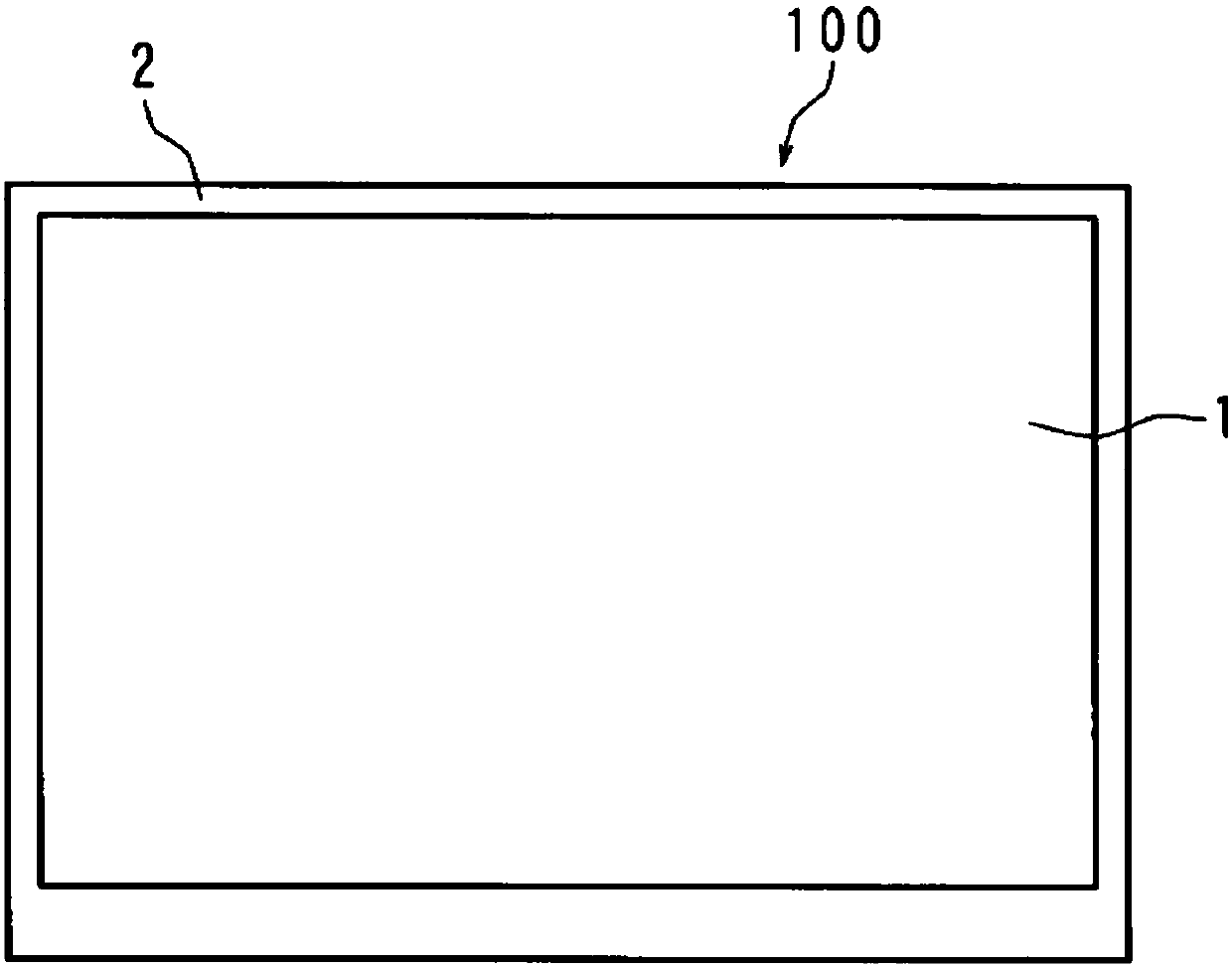
[0043] figure 1 It is a front view showing the appearance of the liquid crystal television receiver 100 in the first embodiment. In the liquid crystal television receiver 100 , the liquid crystal display panel 1 and other components are accommodated in an outer frame 2 and a backlight chassis 6 (storage case) which will be described later.

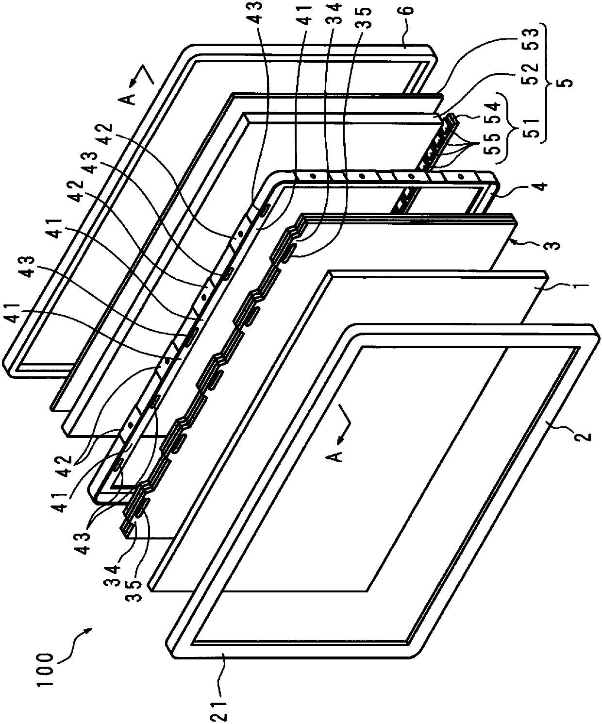
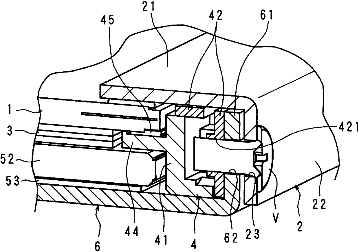
[0044] figure 2 It is an exploded perspective view schematically showing main components constituting the liquid crystal television receiver 100 in the first embodiment. image 3 It is a cross-sectional view schematically showing main components constituting the liquid crystal television receiver 100 in the first embodiment. image 3 yes figure 2 The A-A line section view.

[0045] Such as figure 1 As shown, the liquid crystal television receiver 100 according to the first embodiment has a rectangular liquid crystal display panel 1 on the front side, and the liquid crystal display panel 1 displays images on the surface. In addition...

Embodiment approach 2

[0085] Above, the case where the holding frame 4 , the backlight chassis 6 and the outer frame 2 are jointly fixed by using the fasteners V has been described as an example, but the present invention is not limited thereto.

[0086] Figure 7 It is a perspective view illustrating fixing between the holding frame 4 and the side wall 61 of the backlight chassis 6 in the liquid crystal television receiver 100 according to the second embodiment.

[0087] In Embodiment 2, the mounting member 42 is embedded in the mounted portion 41 of the holding frame 4, and the backlight chassis 6 is arranged in such a manner that the through hole 62 of the side wall 61 matches the fixing hole 421 of the mounted portion 41. The fastener V is inserted into the fixing hole 421 and the through hole 62 . Next, the outer frame 2 is assembled so that the fastener V is covered.

[0088] In the liquid crystal television receiver 100 of Embodiment 2 having the above-mentioned structure, by reliably perf...


PUM


Abstract

Provided is a display device which exhibits improved device thinness and device-border slimness, and makes it possible to definitively position and affix an optical-sheet holding frame. A display device equipped with an optical sheet, a holding frame 4 for surrounding and holding the optical sheet, and a storage housing for housing the optical sheet and the holding frame 4, wherein the holding member 4 is positioned by attaching an attachment member 42 that is stronger than is the holding frame 4 to multiple locations on the holding frame 4, and affixing the attachment member 42 to the storagehousing by using affixing holes 421 formed in the attachment member 42.

Description

technical field [0001] The present invention relates to a display device including an optical sheet, a holding frame surrounding the optical sheet and holding the optical sheet, and a storage case for accommodating the optical sheet and the holding frame. Background technique [0002] In recent years, a display device using a liquid crystal display panel has been widely used. In such a display device, for thinning the thickness of the display device and narrowing the frame width outside the display screen, Various studies have been conducted. [0003] For example, in order to realize thinning or narrowing of the frame of the above-mentioned display device, holding members such as the optical sheet and the light guide plate of the display device are often downsized. However, in the above case, there is a possibility that the strength of the holding member may deteriorate along with the reduction in size of the holding member as described above. [0004] In this regard, the ...

Claims


Application Information

Patent Timeline
Patent Type & Authority Applications(China)
IPC IPC(8): G02F1/1333
CPCG02B6/0088G02F1/133308G02F1/133606G02F1/133317G02F1/133322H04N5/645H04N5/655G02F1/13332
Inventor 杉本有正
Owner SAKAI DISPLAY PROD
Why Eureka
Try Eureka