Mechanical clamp

A fixture and mechanical technology, which is applied in the field of mechanical auxiliary tooling, can solve problems such as danger and safety accidents of locking parts, and achieve the effect of increasing the safety factor, firm installation method, and not easy to cause safety accidents

Inactive Publication Date: 2015-12-09
SUZHOU LONGXINGZHOU IND
View PDF5 Cites 1 Cited by
  • Summary
  • Abstract
  • Description
  • Claims
  • Application Information

AI Technical Summary

Problems solved by technology

[0002] In some mechanical processing operations, such as cutting steel pipes, it is necessary to clamp the steel pipe with a clamping tool to cut the steel pipe, and other cutting operations also use fixtures, but the usual locking parts of the previous fixtures have Bigger problem, because there will be huge force when cutting, if the buckle is not firm, it will easily cause safety accidents, which is very dangerous

Method used


Image

  • Mechanical clamp

Examples


Embodiment Construction

[0011] The present invention will be further illustrated below in conjunction with the accompanying drawings and specific embodiments. This embodiment is implemented on the premise of the technical solution of the present invention. It should be understood that these embodiments are only used to illustrate the present invention and are not intended to limit the scope of the present invention.

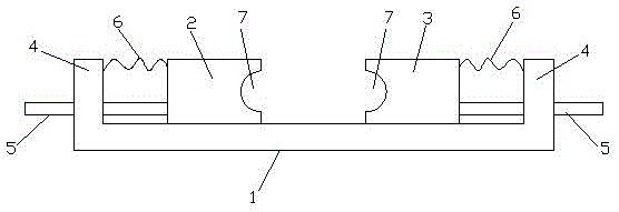
[0012] Such as figure 1 As shown, a kind of mechanical fixture comprises a base 1, a left clamp body 2 and a right clamp body 3; the left and right clamp bodies are respectively placed on the left and right sides of the base 1; and the left and right ends of the base 1 Both are provided with side plates 4; and a push rod 5 is installed on the two side plates 4, and the push rod 5 on the left side plate 4 is connected to the left clamp body 2; the push rod on the right side plate 4 5 is connected to the right clamp body 3.

[0013] Wherein, springs 6 are also connected to the left and r...


PUM


Abstract

The invention discloses a mechanical clamp. The mechanical clamp comprises a base, a left clamp body and a right clamp body, wherein the left clamp body and the right clamp body are respectively put on left and right sides of the base; side plates are arranged at left and right end parts of the base 1, and are respectively provided with a push rod; and the push rod on the left side plate is connected to the left clamp body, and the push rod on the right side plate is connected to the right clamp body. According to the mechanical clamp, clamping holes are formed in the left and right clamp bodies and are used for clamping a workpiece; the push rods are arranged on the left and right clamp bodies, are pushed inward and pressed tightly by virtue of an externally connected machine, and are used for fixing the workpiece in the clamping hole. Compared with a traditional fastener locking assembly mode, the mechanical clamp has the advantages that the pressure-type fixing mode is firmer, and cannot easily cause safety accidents.

Description

technical field [0001] The invention relates to a mechanical auxiliary tooling, specifically a mechanical clamp. Background technique [0002] In some mechanical processing operations, such as cutting steel pipes, it is necessary to clamp the steel pipe with a clamping tool to cut the steel pipe, and other cutting operations also use fixtures, but the usual locking parts of the previous fixtures have Bigger problem, because there will be huge force when cutting, if the lock is not firm, it will easily cause safety accidents, which is very dangerous. Contents of the invention [0003] The purpose of the present invention is to provide a mechanical clamp for the shortcomings of the prior art. [0004] Technical solution: The technical solution adopted by the present invention to solve the problem is: a mechanical clamp, including a base, a left clamp body and a right clamp body; the left and right clamp bodies are respectively placed on the left and right sides of the base;...

Claims


Application Information

Patent Timeline
Patent Type & Authority Applications(China)
IPC IPC(8): B23Q3/06
CPCB23Q3/06
Inventor 黄晓雷黄建华
Owner SUZHOU LONGXINGZHOU IND
Why Eureka
Try Eureka