Clamping mechanism for micro-arc oxidation on top of aluminum alloy piston

A technology of micro-arc oxidation and clamping mechanism, which is applied in the direction of anodic oxidation, electrolytic coating, surface reaction electrolytic coating, etc. It can solve the problems of easily damaged aluminum alloy pistons, falling in the electrolyte, and easy breakage, etc., to achieve fixed The method is stable and firm, avoids electrical conductivity, and improves operability

Inactive Publication Date: 2021-01-29
安徽绿能技术研究院有限公司
View PDF0 Cites 2 Cited by
  • Summary
  • Abstract
  • Description
  • Claims
  • Application Information

AI Technical Summary

Problems solved by technology

[0003] The micro-arc oxidation on the existing production line usually fixes the aluminum alloy piston and then immerses its top in the electrolyte, and uses arc discharge to enhance and activate the reaction on the anode. However, the existing aluminum alloy piston is bound by a wire The fixing method is fixed, and the metal wire also plays the role of electrification. First, the method of fixing with the metal wire is unstable. The metal wire is thin and easy to break during the reaction. After the wire breaks, the aluminum alloy piston will fall into the electrolyte. In the process, the aluminum alloy piston is not easy to take out. Secondly, the metal wire directly contacts the aluminum alloy piston, which is easy to damage the aluminum alloy piston. Finally, the metal wire is soaked in the electrolyte, and the metal wire reacts with the electrolyte, which affects the conductivity of the electrolyte. performance

Method used


Image

  • Clamping mechanism for micro-arc oxidation on top of aluminum alloy piston
  • Clamping mechanism for micro-arc oxidation on top of aluminum alloy piston
  • Clamping mechanism for micro-arc oxidation on top of aluminum alloy piston

Examples


Embodiment

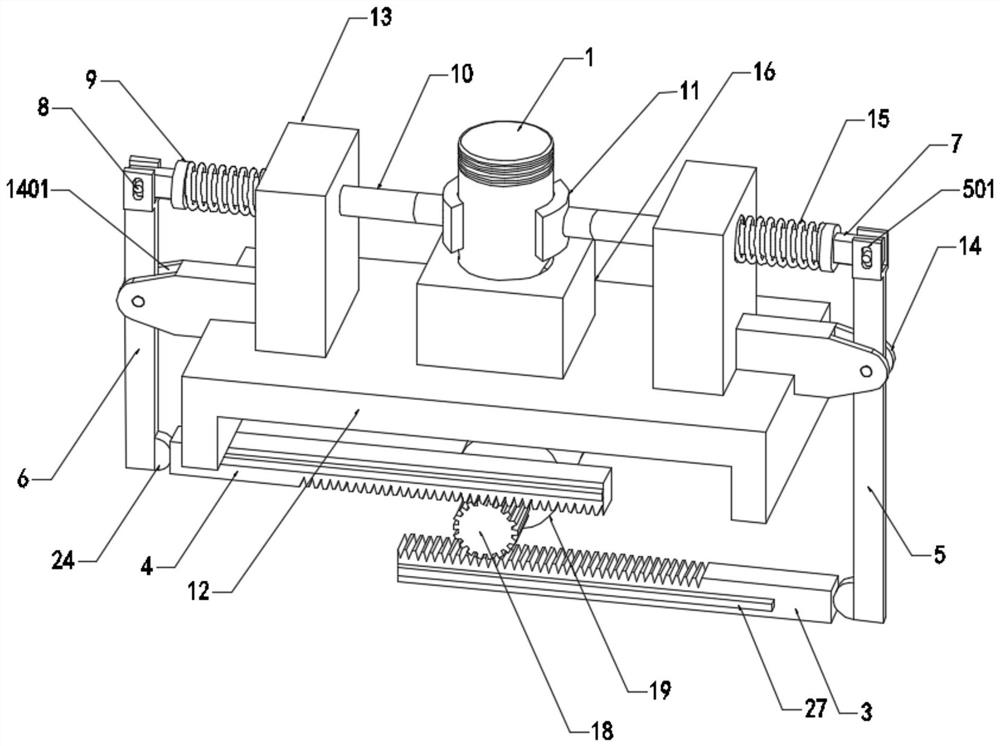
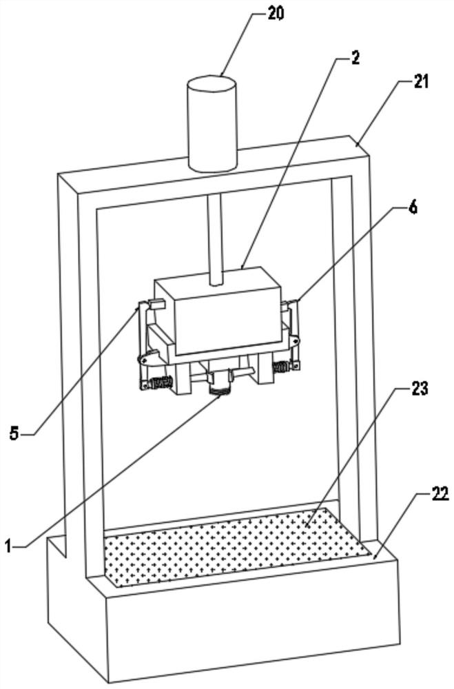
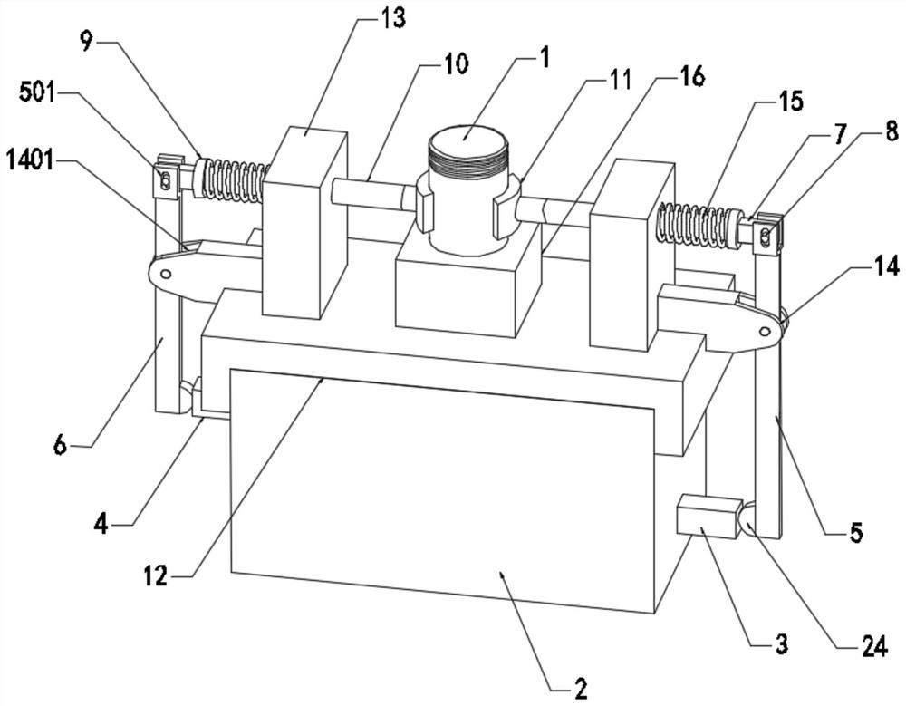
[0046] see Figure 1-10, the present invention provides a technical solution: a clamping mechanism based on micro-arc oxidation on the top of an aluminum alloy piston, including a mounting base 2, a fixing plate 12 is fixedly installed on the top of the mounting base 2, and a fixing plate 12 is fixedly installed on the top of the fixing plate 12 The base 16 is provided with a placement groove 1601 in the base 16, and the conductive rod 17 is fixedly installed in the base 16. Two fixed seats 13 are fixedly installed on the top of the fixed plate 12, and the second mobile slot 1301 is provided in the fixed seat 13. The fixed seat 13 A clamp bar 10 that moves in the second moving groove 1301 is provided inside. A clamp hand 11 is installed on one end of the clamp bar 10. The inner surface wall of the clamp hand 11 is bonded with a rubber layer 26. The other end of the clamp bar 10 is fixedly installed in a limited position. Block 9, the limit block 9 and one end of the second mov...


PUM


Abstract

The invention discloses a clamping mechanism for micro-arc oxidation on the top of an aluminum alloy piston. The clamping mechanism comprises a mounting seat, wherein a fixed plate is fixedly mountedat the top of the mounting seat, a base is fixedly mounted at the top of the fixed plate, a containing groove is formed in the base, a conducting rod is fixedly mounted in the base, two fixed seats are fixedly mounted at the top of the fixed plate, and a second moving groove is formed in each fixed seat. According to the clamping mechanism, an aluminum alloy piston workpiece is placed in the containing groove, a driving motor is started to rotate anticlockwise, a gear is driven to rotate anticlockwise, a first rack plate and a second rack plate are driven to move outwards according to the meshing transmission principle of clamping teeth, a first connecting rod and a second connecting rod are driven to rotate, then clamping rods are driven to move inwards, clamping hands are driven to clampthe aluminum alloy piston workpiece, the aluminum alloy piston workpiece is fixed through the clamping mechanism, the clamping force of the clamping mechanism is large, the fixing mode is stable andfirm, and the operability of the device is improved.

Description

technical field [0001] The invention relates to the technical field of clamping mechanisms, in particular to a clamping mechanism for performing micro-arc oxidation on the top of an aluminum alloy piston. Background technique [0002] As a new type of energy engine, natural gas engine has good economy and less pollutant emission. Due to the characteristics of natural gas, corrosive gas will be generated during combustion. The corrosive gas will corrode the top of aluminum alloy piston at high temperature, resulting in piston corrosion failure. By performing micro-arc oxidation treatment on the top of the aluminum alloy piston, a dense ceramic micro-arc oxidation film is formed on the top surface of the piston, because the micro-arc oxidation film has high hardness, high corrosion resistance, high heat resistance, and high temperature resistance. Impact performance and other advantages, the micro-arc oxidation treatment on the top of the piston can greatly improve its corrosi...

Claims


Application Information

Patent Timeline
Patent Type & Authority Applications(China)
IPC IPC(8): C25D11/04C25D7/00C25D17/08
CPCC25D7/00C25D11/005C25D11/026C25D11/04
Inventor 葛平平魏健吴晓明
Owner 安徽绿能技术研究院有限公司
Why Eureka
Try Eureka