Wall grinding device for building construction

A technology for building construction and walls, applied in the fields of grinding and polishing, which can solve the problems of wall grinding intensity changes and uneven grinding, and achieve the effect of improving the stability of the fixation

Active Publication Date: 2019-10-18
CHONGQING VOCATIONAL INST OF ENG
View PDF7 Cites 2 Cited by
  • Summary
  • Abstract
  • Description
  • Claims
  • Application Information

AI Technical Summary

Problems solved by technology

[0004] The present invention intends to provide a wall grinding device for building construction, so as to solve the problem in the prior art that when the grinding machine is manually pushed, the route deviation causes the wall grinding force to change and cause uneven grinding.

Method used


Image

  • Wall grinding device for building construction
  • Wall grinding device for building construction
  • Wall grinding device for building construction

Examples


Embodiment 1

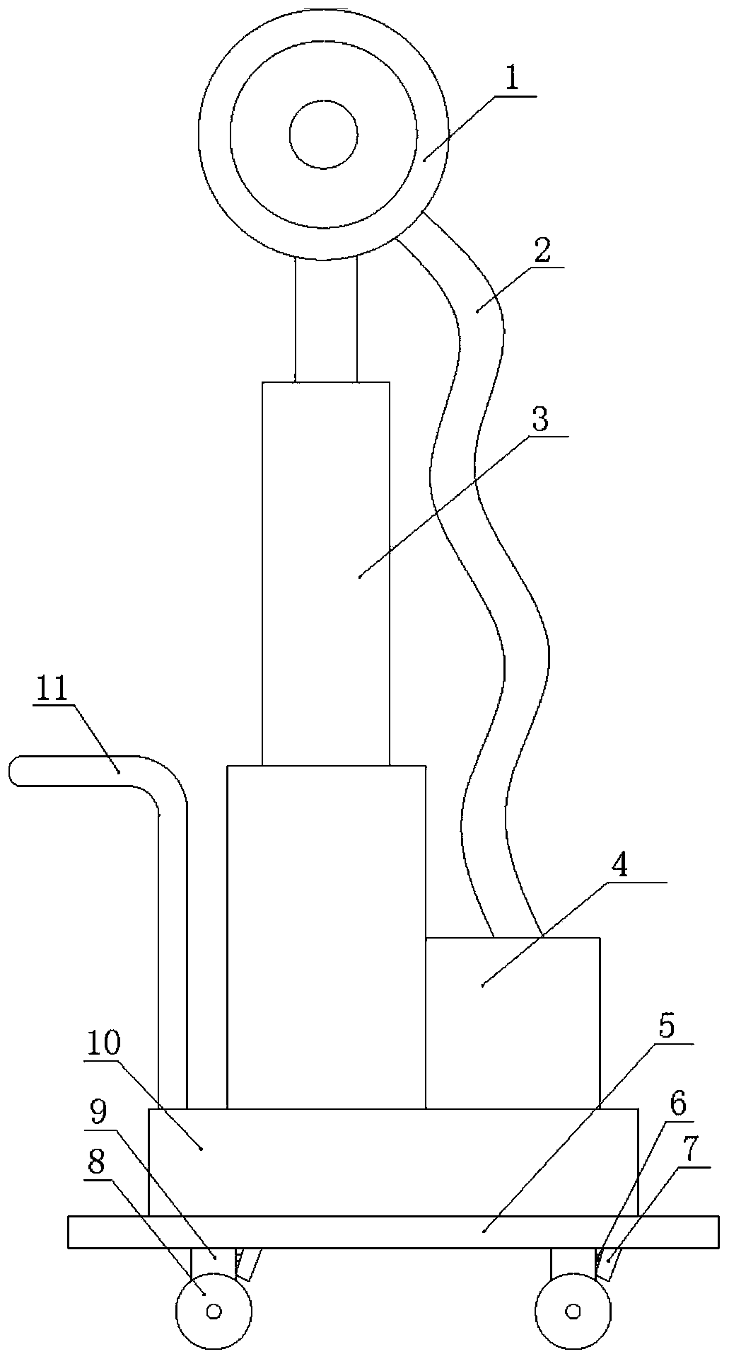
[0026] Such as figure 1 As shown, the wall grinding device for building construction includes a base 10 on which a telescopic rod 3 is vertically installed, and the telescopic rod 3 adopts an electric telescopic rod in the prior art. The top of telescopic rod 3 rotates and is equipped with grinding disc, and grinding disc is connected with motor. The grinding disc outer cover is provided with a dustproof cover 1, a dust collector 4 is installed on the base 10, and a conduit 2 is communicated between the dust collector 4 and the dustproof cover 1, and the conduit 2 adopts a flexible pipe in the prior art.

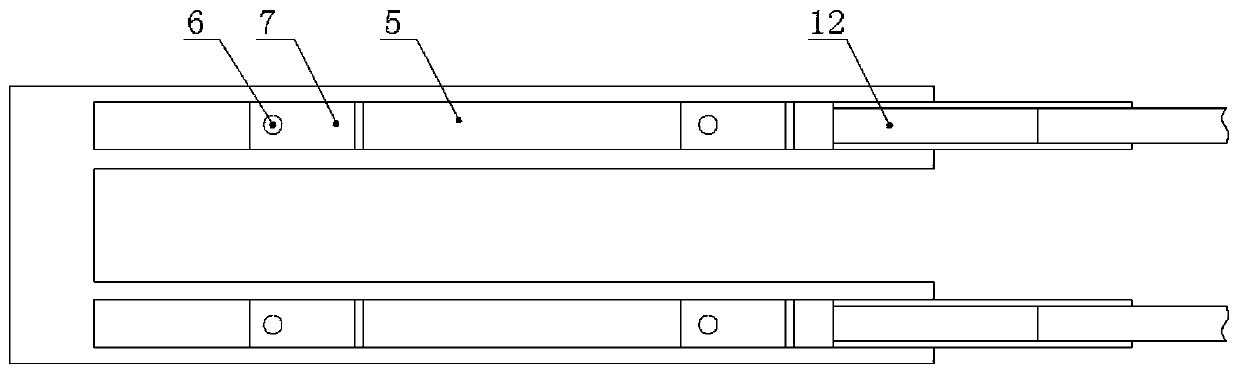
[0027] The bottom of the base 10 is vertically welded with a support column 9, and the bottom of the support column 9 is rotatably connected with a pulley 8, and a push handle 11 is also installed on the base 10 to promote the whole device to move. A guide rail is horizontally installed below the base 10, combined with figure 2 It can be seen that the guide rail includes ...

Embodiment 2

[0039] Such as Figure 4 As shown, the difference between the present embodiment and the first embodiment is that the movable section is hinged at the right end of the fixed section 5 , and the movable section can be folded outwards until it fits with the outer surface of the fixed section 5 . When not in use, the movable section is folded to be attached to the outer surface of the fixed section 5, which can reduce the volume of the present invention and is convenient for placement and carrying. During use, a complete guide rail can be formed for the pulley 8 to slide by turning over the movable section until the fixed section 5 is horizontally connected.

[0040] In order to increase the fixing stability of the movable section, in this embodiment, a first magnet is installed at the free end of the movable section, and a second magnet 17 for being attracted to the first magnet is installed on the fixed section 5 . The fixing stability of the movable section is improved by usi...

Embodiment 3

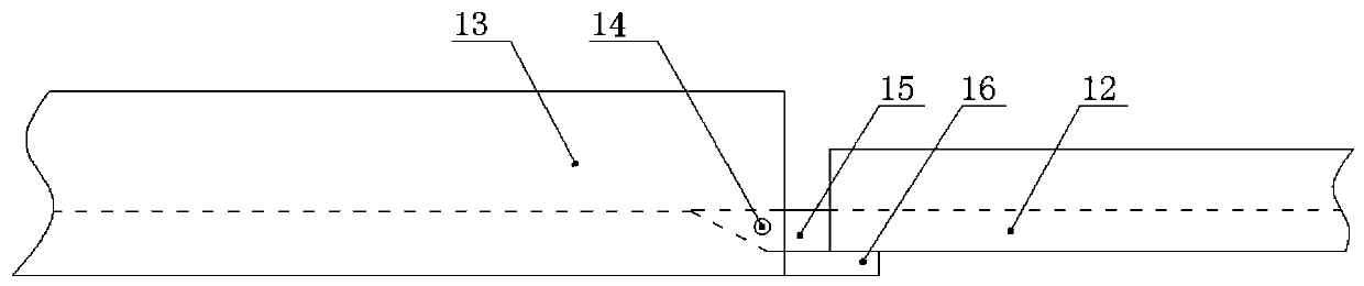
[0042] Such as Figure 5 As shown, the difference between this embodiment and the first embodiment is that a calibration rod 19 is installed horizontally at both ends of one side of the base 10 , and the calibration rod 19 is perpendicular to the side of the base 10 . Calibration rod 19 adopts existing telescopic rod 3, and scale is engraved on the calibration rod 19. In practice, the calibration rod 19 can be pulled out to be against the wall, and the base 10 can be made parallel to the wall by making the lengths of the two calibration rods 19 the same, thereby realizing the calibration of the position of the base 10 . This embodiment is applicable to the situation where a certain distance is required between the base 10 and the wall, and the calibration cannot be achieved by attaching the base 10 to the wall.


PUM


Abstract

The invention relates to the technical field of grinding and polishing, in particular to a wall grinding device for building construction. The wall grinding device comprises a base. Sliding wheels arearranged at the bottom of the base. A telescopic rod is vertically arranged on the base. A grinding disc is arranged at the top of the telescopic rod and connected with a motor. The grinding disc issleeved with a dustproof cover. A dust collector is arranged on the base, and a guide pipe communicates between the dust collector and the dustproof cover. A guide rail is transversely arranged belowthe base and comprises a fixed segment and a moving segment. Lifting holes allowing the sliding wheels to penetrate are formed in the fixed segment. Base plates are hinged to the lifting holes. Torsion springs are arranged at the hinged positions of the base plates. The wall grinding device further comprises a fixing mechanism used for fixing the guide rail. The wall grinding device solves the problems that in the prior art, when a grinding machine is pushed manually, path deviation happens, the wall grinding force changes, and consequently grinding is not uniform.

Description

technical field [0001] The invention relates to the technical field of grinding and polishing, in particular to a wall grinding device for building construction. Background technique [0002] Wall grinding is a very important step in decoration. In order to facilitate wall painting, wallpaper pasting, etc., the wall will be polished and cleaned. The traditional grinding methods are manual grinding with hand-held sandpaper or electric grinding discs, which is time-consuming, laborious and inconvenient to operate. [0003] In order to solve the above problems, a series of semi-automatic grinding machines have appeared in the prior art. This type of grinding machine includes a lifting structure and a pulley, and the grinding of different positions on the wall is realized by manually pushing the grinding machine. However, when the grinder is manually driven, it is inevitable that there will be a route deviation, which will cause the contact pressure between the grinding disc an...

Claims


Application Information

Patent Timeline
Patent Type & Authority Applications(China)
IPC IPC(8): B24B7/18B24B27/00B24B41/02B24B55/00B24B47/12
CPCB24B7/182B24B7/186B24B27/0007B24B41/02B24B47/12B24B55/00
Inventor 马相明
Owner CHONGQING VOCATIONAL INST OF ENG
Why Eureka
Try Eureka