Low flow resistance check valve with high sealing force

A technology of high sealing and bonnet, applied in the direction of valve details, control valves, valve devices, etc., can solve the problems of low flow resistance, high sealing force, and cannot be guaranteed, and achieve the effect of low flow resistance and high sealing force

Inactive Publication Date: 2012-07-11
HANGZHOU CHUNJIANG VALVE
View PDF4 Cites 6 Cited by
  • Summary
  • Abstract
  • Description
  • Claims
  • Application Information

AI Technical Summary

Problems solved by technology

Obviously, if ordinary check valves are used, neither high sealing

Method used


Image

  • Low flow resistance check valve with high sealing force
  • Low flow resistance check valve with high sealing force
  • Low flow resistance check valve with high sealing force

Examples


Embodiment

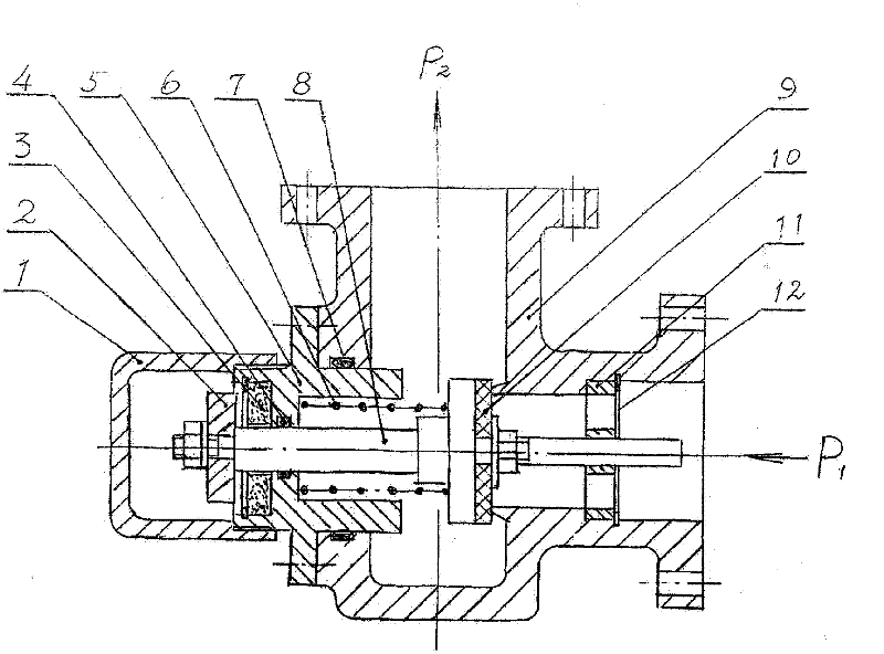
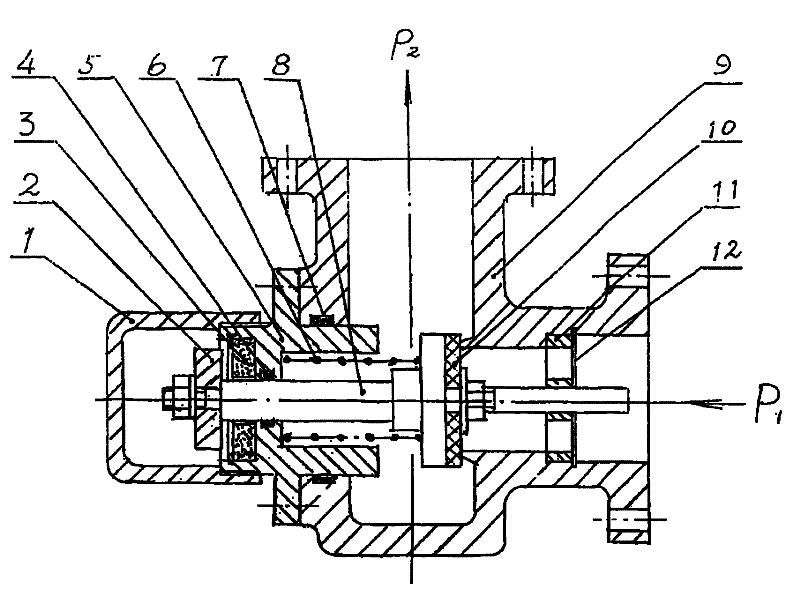
[0037] like figure 1 The shown low-flow prevent back valve with high sealing force consists of protective cover 1, armature 2, permanent magnet 3, O-ring 1 4, valve cover 5, spring 6, O-ring 2 7, valve stem 8 , Valve body 9, gasket 10, guide plate 11, jumper 12 are formed. The center line of the inlet and outlet of the valve body 9 is 90°, and the corresponding flanges are respectively connected with the inlet pipe and the outlet pipe with bolts; the valve cover 5 is installed on the outer plane of the valve body 9 opposite to the inlet flange, and fixed with screws. After installation, the center line of the bonnet 5 is consistent with the center line of the inlet; the permanent magnet 3 is installed in the inner hole of the left end of the bonnet 5, and is positioned with a retaining spring. In order to obtain a strong magnetic force, the material is NdFeB; the guide plate 11 is installed on In the hole of the water inlet, the centerlines of the inner and outer circles are...


PUM


Abstract

The invention relates to a low flow resistance check valve with high sealing force. The low flow resistance check valve is characterized in that the low flow resistance check valve is provided with a valve body, a valve cap and a valve rod, wherein an inlet and an outlet are formed in the valve body; a central line of the inlet and a central line of the outlet of the valve body are arranged by 90 degrees; the valve cap is mounted on an outer plane of the valve body, which is opposite to the inlet; a permanent magnet is mounted in an inner hole of the valve cap; central lines of the valve cap, the valve rod and the inlet are consistent; the valve rod comprises rod parts arranged at two ends of the valve rod and disks positioned on the intermediate sections of the rod parts; the rod parts are respectively matched in holes of the valve cap and a guide plate of the inlet in a sliding way; the disks and corresponding annular blade edges of the valve body form a valve; and a spring is mounted on the valve rod between the disk and the valve cap. Due to the adoption of common action of a strong magnetic force and a spring force, the low flow resistance check valve has the characteristics of high sealing force and low flow resistance.

Description

technical field [0001] The present invention relates to a valve, in particular to a low flow prevent back valve with high sealing force. Background technique [0002] In the pipeline system conveying liquid medium, for various reasons, in order to prevent the backflow of the medium, check valves are generally used, but almost all check valves are expected to have the following characteristics: ① High sealing force, for example, after the check valve is closed Strictly prevent the backflow of the medium, or prevent noise or damage caused by the flutter of the valve core due to the disturbance of the inlet and outlet pressure, because when the valve core is closed, the spring pressure is the smallest; flow resistance. Obviously, if ordinary check valves are used, neither high sealing force nor low flow resistance during circulation can be guaranteed. Contents of the invention [0003] The main purpose of the invention is to overcome the deficiencies of the prior art, so as...

Claims


Application Information

Patent Timeline
IPC IPC(8): F16K15/06F16K27/08
Inventor 柴为民陈永新
Owner HANGZHOU CHUNJIANG VALVE
Why Eureka
Try Eureka