Device for automatic line stopping after yarn breaking

An automatic and yarn-breaking technology, which is applied in textiles, textiles, papermaking, looms, etc., can solve problems such as unreasonable device structure, empty clamping, and inability to achieve effective braking and stopping, and achieve the effect of preventing yarn entanglement

Inactive Publication Date: 2015-12-09
HAIAN QI HONG TEXTILE TECH CO LTD
View PDF1 Cites 4 Cited by
  • Summary
  • Abstract
  • Description
  • Claims
  • Application Information

AI Technical Summary

Problems solved by technology

[0004] This automatic thread stop device for yarn breakage adopts a thread passing wheel and a guide wheel, and uses the method of clamping the yarn at one end to stop the yarn transmission during the thread breakage process. In between, there will be an empty clamp, and effective braking cannot be achieved. At the same time, in the case of continuous power, the wire will be wound on the wire wheel in a large number of cases, and the structure of the device is unreasonable. Therefore, continue to develop a An automatic thread stop device for yarn breakage with reasonable structure and stable automatic thread stop

Method used


Image

  • Device for automatic line stopping after yarn breaking
  • Device for automatic line stopping after yarn breaking

Examples


Embodiment Construction

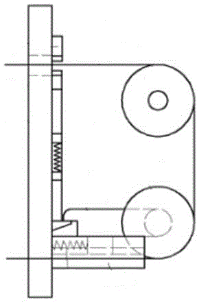
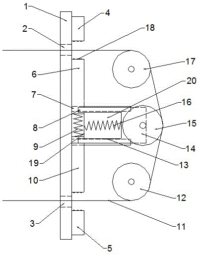
[0019] Such as figure 2 As shown, the present invention discloses an automatic thread stop device for yarn breakage, which includes a vertically arranged frame 1, a clamping device arranged on the upper end of the frame 1, an adjusting device arranged perpendicular to the frame 1, and the side of the adjusting device guide components.

[0020] The upper and lower ends of the frame 1 are respectively provided with a through hole A2 and a through hole B3 for the yarn 11 to pass through.

[0021] The clamping device includes a fixed block A4 arranged on the same axis as the through hole A2 and the through hole B3 and sequentially spaced apart, a clamping device, a fixed block B5 and an outer cover 19 arranged on the outside; a compression spring is arranged in the middle of the clamping device A9, the two ends of the compression spring A9 are respectively connected to the top tight block A6 and the top tight block B10, and a groove 8 is respectively arranged on the side walls o...


PUM


Abstract

The invention relates to a structure of a device for automatic line stopping after yarn breaking, comprising a frame, a clamping device, an adjusting device, and a guide assembly. The clamping device comprises a fixed block A, a tightening device, and a fixed block B. A compression spring A is arranged in the middle of the tightening device, the two ends of the compression spring A are respectively connected with a tightening block A and a tightening block B, and the side wall of the tightening block A and the side wall of the tightening block B are respectively provided with a groove. The adjusting device comprises a pair of guide rails and a sliding block. The guide rails are respectively arranged at the two ends of the compression spring A, and are fixed to the frame. The sliding block is provided with two pins which are respectively inserted into the grooves of the tightening block A and the tightening block B in a matching manner. A compression spring B is arranged inside a cavity. The device is advantageous in that the means of clamping at both sides is adopted when the device suffers from line breakage under an energized condition, and the problem of winding is not caused even if clamping at one end fails; and under the condition of power outage, the tension between yarns disappears, and line conveying is stopped effectively through clamping at both ends.

Description

technical field [0001] The invention relates to an automatic thread stop device for yarn breakage, belonging to the technical field of textile machinery. Background technique [0002] In textile production, yarn is not only the product of the spinning machine, but also the raw material of the loom. Whether in the spinning machine or the loom, the yarn needs a certain tension during the transmission process, and usually needs to go through many A transmission wheel and a guide hole, so the transmission device is ubiquitous. [0003] In the invention patent with the patent number 201420412171.0, an automatic thread stop device for yarn breakage is mentioned, such as figure 1 As shown, it includes a vertical frame, a sliding track fixed horizontally on the frame, and a slide block that can slide horizontally is installed on the slide track, and the outer end of the slide block is equipped with a pass that can rotate from the shaft. Wire wheel, the wire wheel is equipped with ...

Claims


Application Information

Patent Timeline
Patent Type & Authority Applications(China)
IPC IPC(8): D01H13/16D03D51/18
Inventor 刘伟峰
Owner HAIAN QI HONG TEXTILE TECH CO LTD
Why Eureka
Try Eureka