Coil pushing mechanism capable of automatically aligning and transferring fabric coils

A technology of moving mechanism and coil, which is applied in knitting, textile and paper making, etc. It can solve the problems of high efficiency and quality, limited work efficiency, high labor cost, etc., and achieves simple structure, few components and accurate movement high effect

Inactive Publication Date: 2015-12-09
冯加林 +2
View PDF6 Cites 0 Cited by
  • Summary
  • Abstract
  • Description
  • Claims
  • Application Information

AI Technical Summary

Problems solved by technology

[0003] At present, manual methods are generally used to transfer the collar and accessories woven by the flat knitting machine to the sewing machine. Since the collar and accessories are generally woven with relatively dense stitches, the coils to be transferred are many and dense, which is not good for the eyes. People who operate meticulously are not competent, and the work efficiency is limited by the ability of the operator. Once the operation time is long, even the best operator may miss stitches. Can not meet the higher requirements, and the cost of employment is high

Method used


Image

  • Coil pushing mechanism capable of automatically aligning and transferring fabric coils
  • Coil pushing mechanism capable of automatically aligning and transferring fabric coils
  • Coil pushing mechanism capable of automatically aligning and transferring fabric coils

Examples


Embodiment Construction

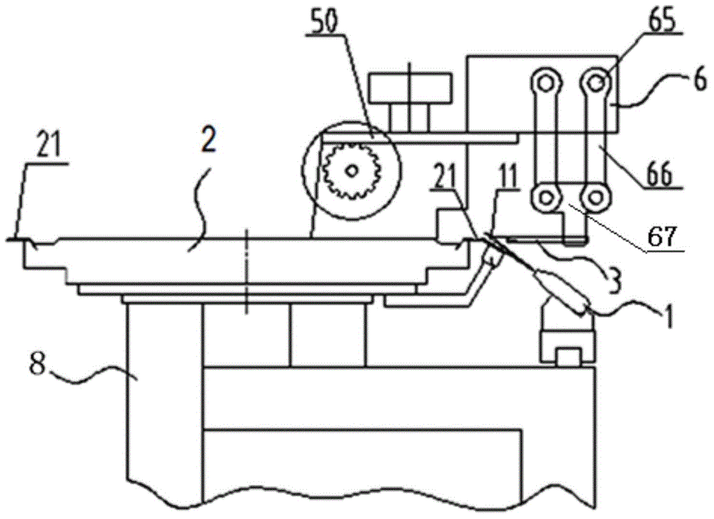
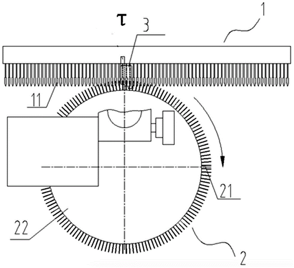
[0033] This application is aimed at figure 1 、 figure 2 and picture The automatic target transfer device shown in 16 is designed.

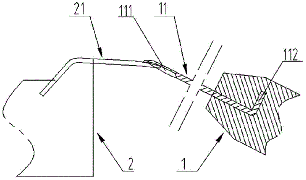
[0034] like figure 1 and figure 2 The first coil automatic eye-to-eye transfer device shown has a sewing machine 2 and a transfer needle plate 1. The sewing machine 2 has a rotating needle plate 22 and grooved needles 21 uniformly distributed along the needle plate. The transfer needle plate 1 is set At the tangential position on one side of the sewing machine dial 22 ( figure 1 shown at the τ position), and can move laterally along the tangential direction, on which a number of parallel and evenly distributed transfer needles 11 are arranged, and the push plate 3 is arranged at the docking position of the transfer needle 11 and the grooved needle 21 (at the τ position above the transfer needle 11, at the docking position, the transfer needle 11 is docked with the grooved needle 21, such as image 3 .

[0035] The rotation of the need...


PUM


Abstract

The invention relates to a coil pushing mechanism capable of automatically aligning and transferring fabric coils. The coil pushing mechanism capable of automatically aligning and transferring the fabric coils comprises a push plate and a push plate transmission unit, wherein the push plate is arranged above a transfer needle which is in butt joint with a groove needle, and is positioned at a position which can be touched connection with a coil on the transfer needle; the push plate transmission unit is connected with the push plate and drives the push plate to synchronously move together with the transfer needle plate and a dial linking machine or drives the transfer needle plate and the groove needle plate to move synchronously; if the transfer needle and the groove needle on the dial linking machine or the groove needle on the groove needle plate move for one needle distance, the push plate synchronously performs reciprocating motion once between the transfer needle plate and the dial linking machine or between the transfer needle plate and the groove needle plate, so that the coil on the transfer needle is pushed to the corresponding groove needle and then returned to an initial position, and reciprocating motion of next needle distance is prepared. The coil pushing mechanism has the advantages that coil transfer is reliable and accurate, needle leakage does not occur; even if moving in multiple directions, a reciprocating motion unit which is used for pushing the push plate to move, is driven by only one power force; furthermore, the coil pushing mechanism is simple in structure, less in composition parts, high in movement accuracy, reliable in action and low in cost.

Description

technical field [0001] The invention relates to a knitting machine, in particular to a coil pushing mechanism for automatic transfer of fabric coils to the target. Background technique [0002] The garment parts, collar and accessories of the knitted sweater are woven separately, and then stitched by a seaming machine. Before sewing, the knitted collar and accessories need to be transferred to the seaming machine. [0003] At present, manual methods are generally used to transfer the collar and accessories woven by the flat knitting machine to the sewing machine. Since the collar and accessories are generally woven with relatively dense stitches, the coils to be transferred are many and dense, which is not good for the eyes. People who operate meticulously are not competent, and the work efficiency is limited by the ability of the operator. Once the operation time is long, even the best operator may miss stitches. Higher requirements cannot be met on the surface, and the co...

Claims


Application Information

Patent Timeline
IPC IPC(8): D04B37/00
Inventor 冯加林冯天元巫友群
Owner 冯加林
Why Eureka
Try Eureka