Method and device for reducing exciting current of transformer during bypass conduction of isolating uninterrupted power supply (UPS)

A technology of excitation current and transformer, which is applied in the field of UPS to improve the problem of large excitation current, reduce the excitation current, and ensure reliable operation

Active Publication Date: 2015-12-09
ZHANGZHOU KEHUA ELECTRIC TECH CO LTD
View PDF7 Cites 6 Cited by
  • Summary
  • Abstract
  • Description
  • Claims
  • Application Information

AI Technical Summary

Problems solved by technology

It can be seen that these two methods have certain d

Method used


Image

  • Method and device for reducing exciting current of transformer during bypass conduction of isolating uninterrupted power supply (UPS)
  • Method and device for reducing exciting current of transformer during bypass conduction of isolating uninterrupted power supply (UPS)
  • Method and device for reducing exciting current of transformer during bypass conduction of isolating uninterrupted power supply (UPS)

Examples


Embodiment Construction

[0031] The present invention will be further described below in conjunction with the drawings and specific embodiments.

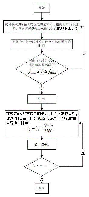
[0032] Such as Figure 1~4 As shown, a method for reducing the magnetizing current of a transformer in an isolated UPS bypass conduction implemented by the present invention includes the following steps:

[0033] Step S1: Obtain the zero-crossing point of the UPS input AC power in real time, and obtain the frequency f of the UPS input AC power according to the time difference between two adjacent zero-crossing points;

[0034] Step S2: Determine whether the frequency f of UPS input AC power satisfies f min ≤f≤f max , Where f min And f max They are the minimum threshold and the maximum threshold of the AC frequency in the normal range of UPS bypass output, if they are met, go to step S3, otherwise return to step S1;

[0035] Step S3: Take the initial value of a to 1, where a is a positive integer;

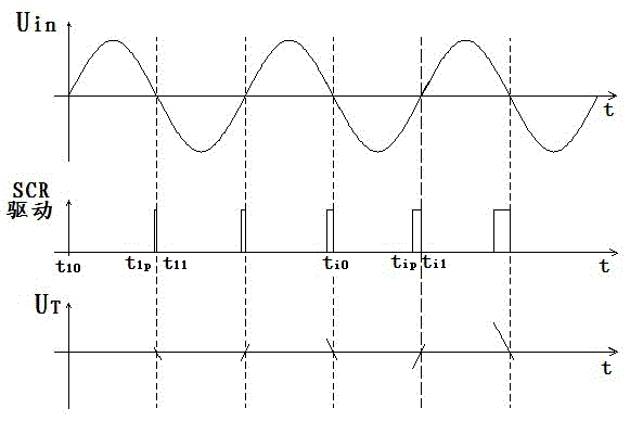
[0036] Step S4: In the current i-th half sine wave cycle of the AC...


PUM


Abstract

The invention relates to a method and a device for reducing exciting current of a transformer during bypass conduction of isolating uninterrupted power supply (UPS). The method comprises the following steps: (S1) acquiring zero crossing points of alternating current input by the UPS in real time, and acquiring the frequency f of the alternating current input by the UPS according to the time difference between the adjacent two zero crossing points; (S2) judging whether the frequency f of the alternating current input by the UPS meets the conditions that f is less than or equal to fmax and greater than or equal to fmin or not, if so, entering the step (S3), or else, returning to the step (S1); (S3) taking an initial value of a as 1, wherein a is a positive integer; (S4) in current ith half-sine wave period of the alternating current input by the UPS, controlling a bypass silicon controlled rectifier (SCR) to be in a conducting state by the UPS in the period from the moment tip to the moment of the adjacent next zero crossing point ti1, wherein the formula is as shown in the specification; and (S5) progressively increasing the value of a, judging whether a is less than or equal to N-1 or not, if so, returning to the step (S4), or else, ending. The method and the device have the beneficial effects that the minimum exciting current output from the isolating transformer is ensured; and the bypass SCR is not damaged.

Description

Technical field [0001] The invention relates to the field of UPS, and in particular to a method and a device for reducing the excitation current of a transformer in an isolated UPS bypass. Background technique [0002] With the continuous development of UPS applications, the isolation requirements for UPS systems are constantly being proposed. The application of fully isolated UPS can effectively ensure the safety and reliability of user equipment systems. From the design structure, fully isolated systems and traditional non-isolated systems The difference of the system is the addition of an output or input isolation transformer, which isolates the entire UPS system from the load system to ensure that the load system is not affected by interference signals at the input. However, the application of isolation transformers must consider the impact of the excitation current on the UPS system. According to the characteristics of the transformer, the transformer can be regarded as an i...

Claims


Application Information

Patent Timeline
IPC IPC(8): H02P13/00
CPCH02P13/00
Inventor 曹振华黄振民陈君
Owner ZHANGZHOU KEHUA ELECTRIC TECH CO LTD
Why Eureka
Try Eureka