
Vacuum sealed type 3D printing device

A 3D printing and vacuum sealing technology, applied in the direction of additive processing, etc., can solve problems such as affecting the strength and quality of molded products, inability to flatten more, and limited flattening effect, and achieve good tiling effect, stable speed, and product quality. good quality effect

Inactive Publication Date: 2015-12-16
SHAOXING UNIVERSITY
View PDF7 Cites 12 Cited by
  • Summary
  • Abstract
  • Description
  • Claims
  • Application Information

AI Technical Summary

Problems solved by technology

[0002] In the existing 3D printing equipment, the printing box is generally an ordinary box, and a powder spreading device is installed in the box, and the powder is poured into the box to spread the powder before 3D printing. The outside air is connected, so that during laser printing, the impurities in the outside air will affect the printing effect and affect the strength and quality of the formed product
[0003] Moreover, in the existing 3D printers, the rolling of the powder is only carried out by rolling rollers, and the rolling is only to prevent the powder from protruding, so as to compact it. When compacting, when the powder is too concentrated in some places , it cannot be further flattened, and its flattening effect is limited
[0004] Moreover, the existing powder feeding mechanism generally uses the rotation of the screw to realize the delivery, and because the nano-scale powder is easy to stick inside the delivery tube, it affects the delivery, and it is easy to affect the delivery accuracy

Method used


Image

  • Vacuum sealed type 3D printing device
  • Vacuum sealed type 3D printing device
  • Vacuum sealed type 3D printing device

Examples


Embodiment Construction

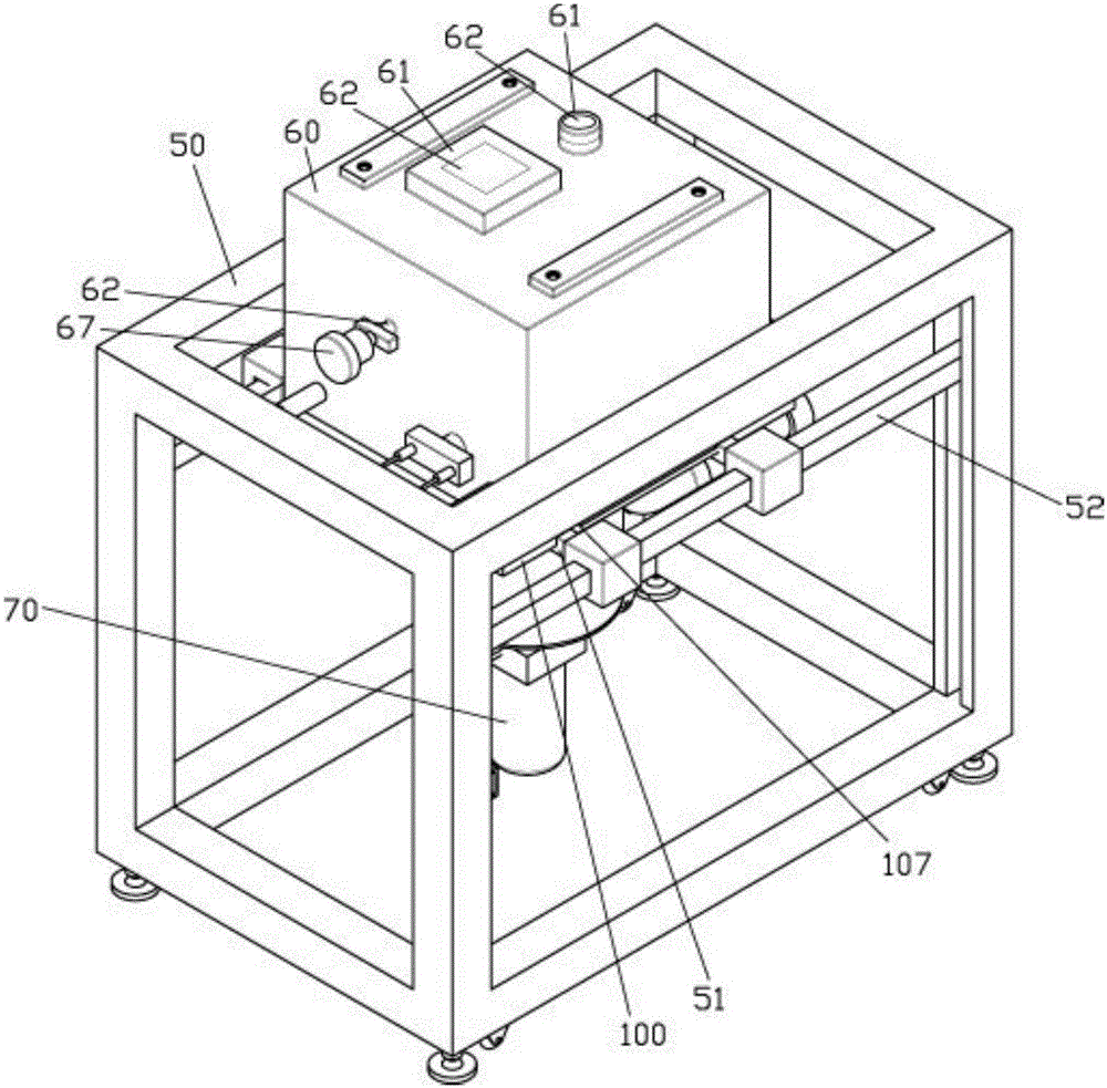
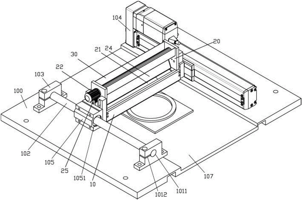
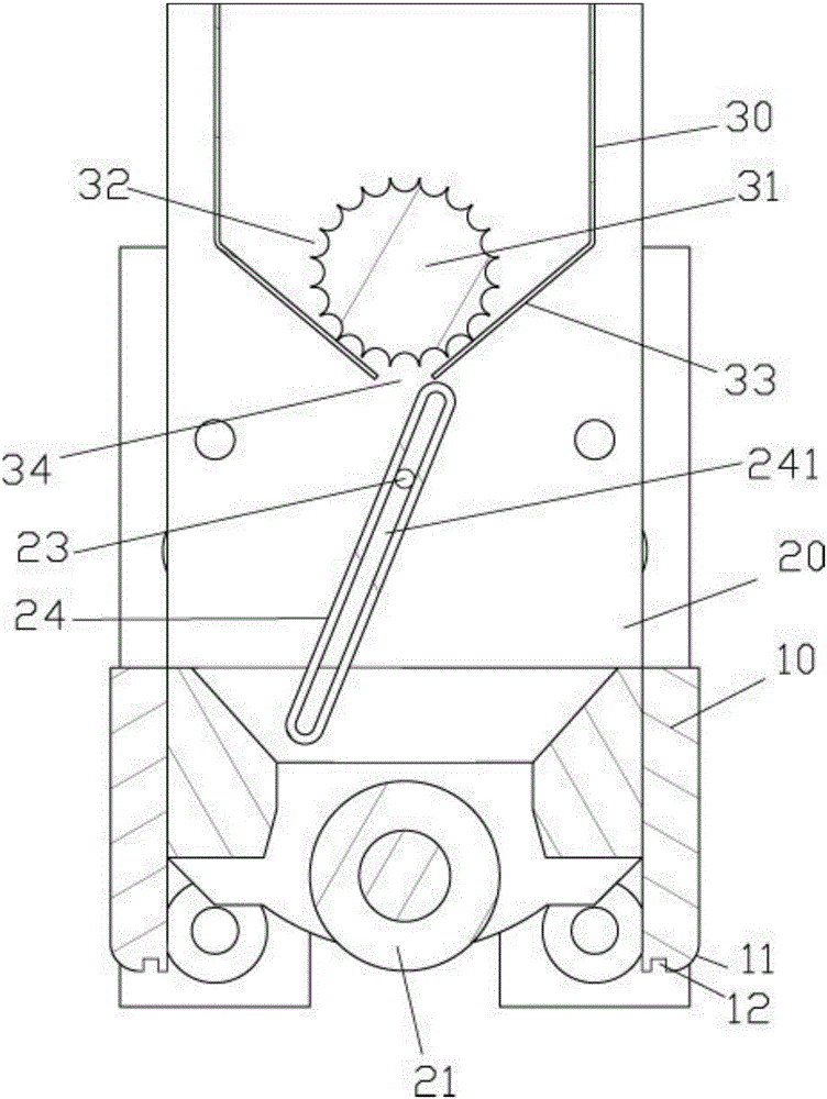
[0029] Examples, see e.g. Figures 1 to 6 As shown, a vacuum-sealed 3D printing device includes a frame-shaped frame body 50 and a laying powder feeding device. The middle part of the frame-shaped frame body 50 is fixed with a transverse beam 51, and the transverse beam 51 is fixed with a powder-spreading bottom plate 100. A box body 60 is fixed on the powder floor 100, the top surface of the box body 60 has an observation hole 61, the top surface of the box body 60 is fixed with a quartz glass block 62, the quartz glass block 62 covers the observation hole 61, and the side wall of the box body 60 The upper connection is connected with an air intake pipe 63, and the air intake pipe 63 communicates with the side wall through hole 64 provided on the side wall of the casing 60. The bottom surface of the edge of the powder floor 100 is connected with an exhaust pipe 65, and the edge of the powder floor 100 The bottom has a bottom through hole 66, and the bottom through hole 66 com...


PUM


Abstract

The invention discloses a vacuum sealed type 3D printing device. The device comprises a frame-form rack and a flat-laying powder conveying device, a transverse beam is fixed to the middle of the frame-form rack, a powder laying base plate is fixed to the transverse beam, a box body is fixed to the powder laying base plate, observation holes are formed in the top face of the box body, quartz glass blocks are fixed to the top face of the box body, the quartz glass blocks cover the observation holes, an air inlet pipe is connected with the side wall of the box body in a communicated mode, the air inlet pipe is communicated with a side wall through hole formed in the side wall of the box body, a vent pipe is connected with the bottom face of the side portion of the powder laying base plate in a communicated mode, and a bottom through hole is formed in the side portion of the powder laying base plate; the flat-laying powder conveying device is arranged inside the box body; the flat-laying powder conveying device comprises a flat-laying rack and a powder storage groove, the flat-laying rack is a rectangular frame, and scraper plates are fixedly connected with the outer walls of a left side plate and a right side plate of the flat-laying rack through bolts. By means of the vacuum sealed type 3D printing device, it can be guaranteed that air cannot enter a vacuum box, thereby it is guaranteed that the quality of products obtained through 3D printing conducted in the vacuum box is good, in addition, a tooth-form groove of a conveying roller is adopted for conveying, and the conveying precision of the device is high.

Description

Technical field: [0001] The invention relates to the technical field of 3D printing equipment, and more specifically relates to a vacuum-sealed 3D printing device. Background technique: [0002] In the existing 3D printing equipment, the printing box is generally an ordinary box, and a powder spreading device is installed in the box, and the powder is poured into the box to spread the powder before 3D printing. The outside air is connected, so that during laser printing, the impurities in the outside air will affect the printing effect and affect the strength and quality of the formed product. [0003] Moreover, in the existing 3D printers, the rolling of the powder is only carried out by rolling rollers, and the rolling is only to prevent the powder from protruding, so as to compact it. When compacting, when the powder is too concentrated in some places , it cannot be further flattened, and its flattening effect is limited. [0004] Moreover, the existing powder feeding m...

Claims


Application Information

Patent Timeline
Patent Type & Authority Applications(China)
IPC IPC(8): B22F3/00B33Y30/00B22F10/28B22F12/00B22F12/60B22F12/63
Inventor 吴继华张新华何绍木闫庆军闫书恒
Owner SHAOXING UNIVERSITY
Learn More