Connecting device

A technology of connecting devices and connecting bodies, which is applied in the direction of joints, manipulators, manufacturing tools, etc., can solve problems such as difficult maintenance work, and achieve the effects of short operation time, firm fixation, and safety

Active Publication Date: 2015-12-16
CHINA NUCLEAR POWER ENG CO LTD
View PDF10 Cites 3 Cited by
  • Summary
  • Abstract
  • Description
  • Claims
  • Application Information

AI Technical Summary

Problems solved by technology

Generally, the wall-through component is installed on the protective wall in front of the hot cell (the hot cell is a shielded small room for high-radioactivity tests and operations, which is isolated from the surrounding environment), the active arm is installed in the front area of ​​the hot cell (that is, the safe operation area), and the driven The arm is i

Method used


Image

  • Connecting device
  • Connecting device
  • Connecting device

Examples


Embodiment Construction

[0024] The present invention will be further described below in conjunction with the accompanying drawings and specific embodiments.

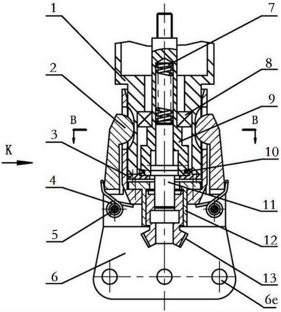
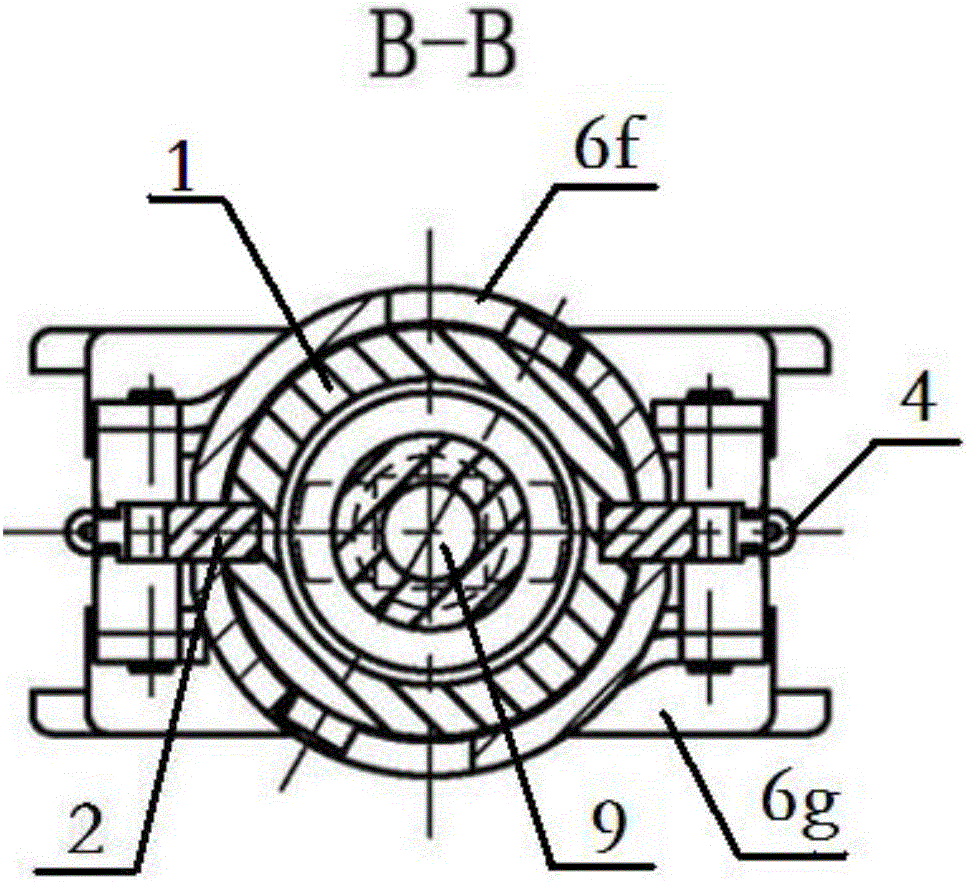
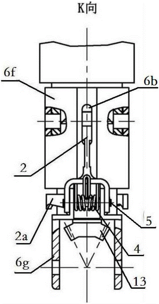
[0025] Such as Figure 1a-Figure 1c As shown, a connection device provided by the present invention is composed of a "lower connection assembly" and an "upper connection assembly", including a connection body 6, a locking arm 2 arranged outside the connection body 6, and a locking arm 2 arranged on the connection body 6. The support sleeve 12 in the body 6, the bevel gear 13 arranged in the support sleeve 12 (the above components form the "lower connection assembly"); also includes the bearing seat 1 that can be plugged in the connection body 6, the A hollow shaft sleeve 9 is pierced in the bearing seat 1, and the closed top end of the shaft sleeve 9 protrudes upwards outside the bearing seat 1. A spring 7 and a transmission shaft 11 are arranged inside the shaft sleeve 9. The shaft sleeve 9 The opening at the bottom end is provided with a reta...


PUM


Abstract

The invention belongs to the field of mechanical separation and connection, and particularly relates to a connecting device. The connecting device comprises a connecting body, a locking arm arranged on the outer side of the connecting body, a supporting sleeve arranged in the connecting body, a bevel gear arranged in the supporting sleeve and a bearing seat capable of being inserted in and pulled out of the connecting body. A hollow shaft sleeve penetrates through the bearing seat, the sealed top end of the shaft sleeve protrudes upwards out of the bearing seat, and a spring and a transmission shaft are arranged in the shaft sleeve. A baffle ring blocking separation of the transmission shaft is arranged at the bottom end of the shaft sleeve, the spring squeezes the transmission shaft to the direction of an opening in the bottom end of the shaft sleeve, and the end, away from the spring, of the transmission shaft protrudes out of the bottom of the shaft sleeve and can be connected with or separated from the top of the bevel gear along with inserting and pulling of the bearing seat in the connecting body. An end cover blocking separation of the shaft sleeve is arranged at the bottom end of the bearing seat, and a bearing is arranged between the bearing seat and the shaft sleeve. An operator can remotely mount and separate the connecting device in a hot chamber by operating a mechanical arm, so that operation is simple and rapid, the repairing cost is reduced, and meanwhile, the radiation risk to the operator is avoided.

Description

technical field [0001] The invention belongs to the field of mechanical separation and connection, and in particular relates to a connection device. Background technique [0002] The manipulator used in nuclear engineering is mainly composed of three parts: the active arm, the wall-through component (or electronic control system), and the slave arm. Transfer the motion to the slave arm so that the motion of the slave arm exactly matches the motion of the master arm. Generally, the wall-through component is installed on the protective wall in front of the hot cell (the hot cell is a shielded small room for high-radioactivity tests and operations, which is isolated from the surrounding environment), the active arm is installed in the front area of ​​the hot cell (that is, the safe operation area), and the driven The arm is installed in a radioactive and corrosive thermal chamber. When the clamp on the slave arm fails and needs to be repaired or replaced, the maintenance perso...

Claims


Application Information

Patent Timeline
IPC IPC(8): B25J17/00
Inventor 沈琛林彭思胡国辉陈丽惠梁汝囡
Owner CHINA NUCLEAR POWER ENG CO LTD
Why Eureka
Try Eureka