Power bogie and light rail vehicle
A technology for power bogies and power wheels, applied to bogies, devices for lateral relative movement between underframes and bogies, operating mechanisms for railway vehicle brakes, etc., can solve the problem of increasing the natural frequency of bogie nodding and ups and downs , braking device, bogie side beam and end beam joints are prone to vibration fatigue and other problems, so as to reduce the natural frequency of nodding and ups and downs, improve stability and safety, and improve the passing capacity
- Summary
- Abstract
- Description
- Claims
- Application Information
AI Technical Summary
Problems solved by technology
Method used
Image
Examples
Embodiment 1
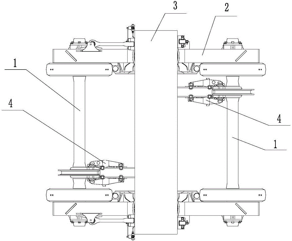
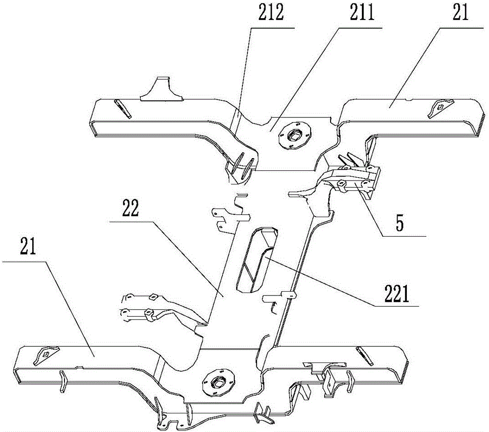
[0033] figure 1 It is the first structural diagram of the first embodiment of the power bogie of the present invention; figure 2 It is a schematic diagram of the second structure of the first embodiment of the power bogie of the present invention; please refer to Figure 1-2 , The embodiment of the present invention provides a power bogie, including: a power wheel set 1, a frame 2, a bolster 3, and a basic braking device 4.
[0034] Specifically, the frame includes two parallel side beams 21 and a cross beam 22 connecting the two side beams 21. The cross beam 22 is plate-shaped. The plate-shaped cross beam 22 can avoid stress concentration during the butting process with the side beams 21, thereby The structural strength of the frame 2 is ensured; among them, the side beam 21 and the cross beam 22 are single-box panel welded structures, so that the cross beam 22 and the side beam 21 have long welds at the upper and lower cover plates, thereby ensuring the welding performance The ...
Embodiment 2
[0037] This embodiment further supplements the power bogie of the above embodiment.
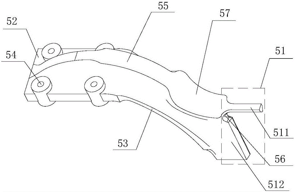
[0038] image 3 It is a schematic diagram of the structure of the second embodiment of the power bogie of the present invention; please refer to image 3 On the basis of the first embodiment, further, the brake hanger 5 may include: a welding section 51, an installation section 52, and a transition section 53 connecting the welding section 51 and the installation section 52.
[0039] Specifically, the transition section 53 is arc-shaped, the installation section 52 is plate-shaped, the installation section 52 is provided with at least two fastener installation holes 54 for installing the basic brake device 4, the installation section 52 and the transition section 53 are A web 55 is provided. The web 55 is arc-shaped, and the convex part of the arc is upward. Preferably, the thickness of the web 55 reaches the maximum at the connection between the mounting section 52 and the welding section 51 to im...
Embodiment 3
[0043] This embodiment further supplements the power bogie of the above embodiment.
[0044] Figure 4 It is the first structural diagram of the third embodiment of the power bogie of the present invention; Figure 5 It is a schematic diagram of the second structure of the third embodiment of the power bogie of the present invention; Image 6 It is the third structural diagram of the third embodiment of the power bogie of the present invention; please refer to Figure 4-5 On the basis of Embodiment 1 and / or Embodiment 2, the power bogie may also include: a primary suspension device, the primary suspension device includes a primary spring 6, and the primary spring 6 is provided on the power wheelset 1 and the frame 2. In between, the arrangement of the primary spring 6 can reduce the wear between the wheel and the rail surface, and the arrangement of the primary spring 6 can also reduce the swing and rolling angle of the bogie, and can reduce the running noise. In addition, since ...
PUM
 Abstract
Description
Claims
Application Information
 - R&D
- Intellectual Property
- Life Sciences
- Materials
- Tech Scout
- Unparalleled Data Quality
- Higher Quality Content
- 60% Fewer Hallucinations
Browse by: Latest US Patents, China's latest patents, Technical Efficacy Thesaurus, Application Domain, Technology Topic, Popular Technical Reports.
© 2025 PatSnap. All rights reserved.Legal|Privacy policy|Modern Slavery Act Transparency Statement|Sitemap|About US| Contact US: help@patsnap.com


