Height restriction frame on road

A road and height-limiting technology, which is applied in the field of road-limited elevated structures, can solve problems such as poor road traffic, hindering traffic operation, and damage to elevated-limited structures, so as to reduce vehicle damage and personnel injuries, prolong impact time, and reduce The effect of impact force

Active Publication Date: 2015-12-16
黄飞
View PDF6 Cites 14 Cited by
  • Summary
  • Abstract
  • Description
  • Claims
  • Application Information

AI Technical Summary

Problems solved by technology

The common structure of the height limiter is generally in the shape of a door, which is composed of two columns and the height limit beam on the top. When the super high vehicle passes by forcibly, it will hit the top height limit beam, thereby restricting the passage of the super high vehicle
[0003] At present, when common height-limiting structures are hit by super-height vehicles, due to the huge mutual impact between the height-limiting beams and super-height vehicles in a short period of time, there may be the following problems: (1) The height-limiting beams on the top of the height-limiting structure fall off, (2) Cause damage to vehicles, especially when the impact speed is high, it is likely to cause injury to personnel; (3) Falling off the height-limiting beam and falling to the ground will hinder normal traffic operation; ( 4) The repair of the height-limited viaduct requires re-welding or other fixed connection work on the height-limited beams, which is not only time-consuming and labor-intensive, but also has a negative impact on road traffic

Method used


Image

  • Height restriction frame on road
  • Height restriction frame on road
  • Height restriction frame on road

Examples


Embodiment Construction

[0037] In order to make the object, technical solution and advantages of the present invention clearer, the present invention will be further described in detail below in conjunction with the accompanying drawings and embodiments. It should be understood that the specific embodiments described here are only used to explain the present invention, not to limit the present invention. In addition, the technical features involved in the various embodiments of the present invention described below can be combined with each other as long as they do not constitute a conflict with each other.

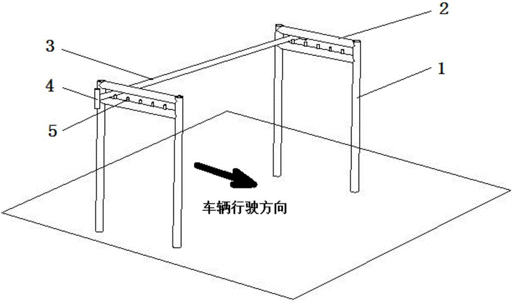
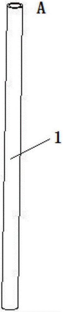
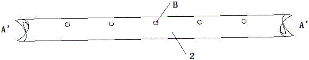
[0038] figure 1 It is a schematic diagram of a height-limiting structure according to an embodiment of the present invention, figure 2 for figure 1 Schematic diagram of the structure of the central column, image 3 for figure 1 Schematic diagram of the middle support beam structure, Figure 4 for figure 1 Schematic diagram of the mid-height beam and short beam structure, Figure 5 for f...


PUM


Abstract

The invention discloses a height restriction frame on a road, and belongs to the field of road safety. The height restriction frame comprises stand columns, supporting beams, a height restriction cross beam and stop bars. The stand columns are arranged on the two sides of the road respectively. The supporting beams are fixed to the upper ends of the stand columns to be supported by the stand columns to be located above the road. The supporting beams are parallel to the direction of the road and are provided with the stop bars in the length direction of the supporting beams. The height restriction cross beam is transversely arranged on the supporting beams and stopped by the stop bars. The stop bars allow the height restriction cross beam to slide in the length direction of the supporting beams by means of bending deformation of the stop bars when the height restriction cross beam is bumped by a vehicle. The height restriction frame on the road is safer, more economical and more convenient to maintain and use.

Description

technical field [0001] The invention belongs to the field of road safety, and more specifically relates to a road height-limiting viaduct structure. Background technique [0002] Elevation-limited viaduct structures are generally used in bridges, tunnels and other places where the height of vehicles is limited. Its function is to hinder the passage of super-high vehicles, thereby avoiding damage to bridges, tunnels, etc. The common structure of the height limiter is generally in the shape of a door, which is composed of two columns and the height limit beam on the top. When the super high vehicle passes by forcibly, it will hit the top height limit beam, thereby restricting the passage of the super high vehicle. [0003] At present, when common height-limiting structures are hit by super-height vehicles, due to the huge mutual impact between the height-limiting beams and super-height vehicles in a short period of time, there may be the following problems: (1) The height-lim...

Claims


Application Information

Patent Timeline
Patent Type & Authority Applications(China)
IPC IPC(8): E01F13/00
Inventor 黄飞魏俊红
Owner 黄飞
Why Eureka
Try Eureka