Built-in driving support mechanism hydraulic dam and its application method

A support mechanism, built-in technology, applied in water conservancy engineering, marine engineering, coastline protection, etc., can solve the problems of large space occupation, high construction cost, and sedimentation of the driving cylinder, so as to keep the dam surface clean and improve the use of Longevity and the effect of reducing the failure rate

Active Publication Date: 2017-08-11
WUHU YINHONG HYDRAULIC COMPONENTS
View PDF8 Cites 0 Cited by
  • Summary
  • Abstract
  • Description
  • Claims
  • Application Information

AI Technical Summary

Problems solved by technology

[0003] In the process of realizing the present invention, the inventors found that the prior art has at least the following problems: the driving oil cylinder has been subjected to sedimentation for a long time, resulting in heavy pollution, strong corrosion, and high failure rate
Traditional support rods need to be equipped with sliding guide grooves, reserved foundation pits, and secondary pouring of embedded parts. The construction cost is high and the process is complicated
The traditional support rods cannot be lifted to release the dam when the power is off. When the flood surges and the power is lost, the dam cannot be released in time to discharge the flood, which affects the safety of the dam surface.
The traditional support rods extend outward along the sliding guide groove when the dam is placed, and are exposed outside the dam surface, which takes up a lot of space and affects the overall aesthetic effect

Method used


Image

  • Built-in driving support mechanism hydraulic dam and its application method
  • Built-in driving support mechanism hydraulic dam and its application method
  • Built-in driving support mechanism hydraulic dam and its application method

Examples


Embodiment 1

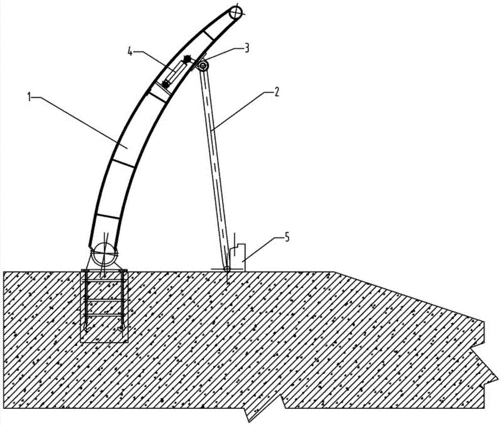
[0051] see Figure 1-3 As shown, the built-in drive support mechanism hydraulic dam has:

[0052] Dam body;

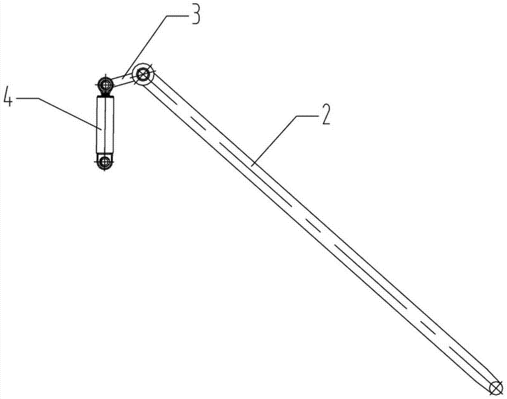
[0053] A telescopic cylinder arranged along the height direction of the dam body and installed on the dam body;

[0054] a link arm, the first end of which is hinged to the piston rod of the telescopic cylinder;

[0055] The support rod used to support the dam body, the upper end of the support rod is fixedly connected with the second end of the link arm.

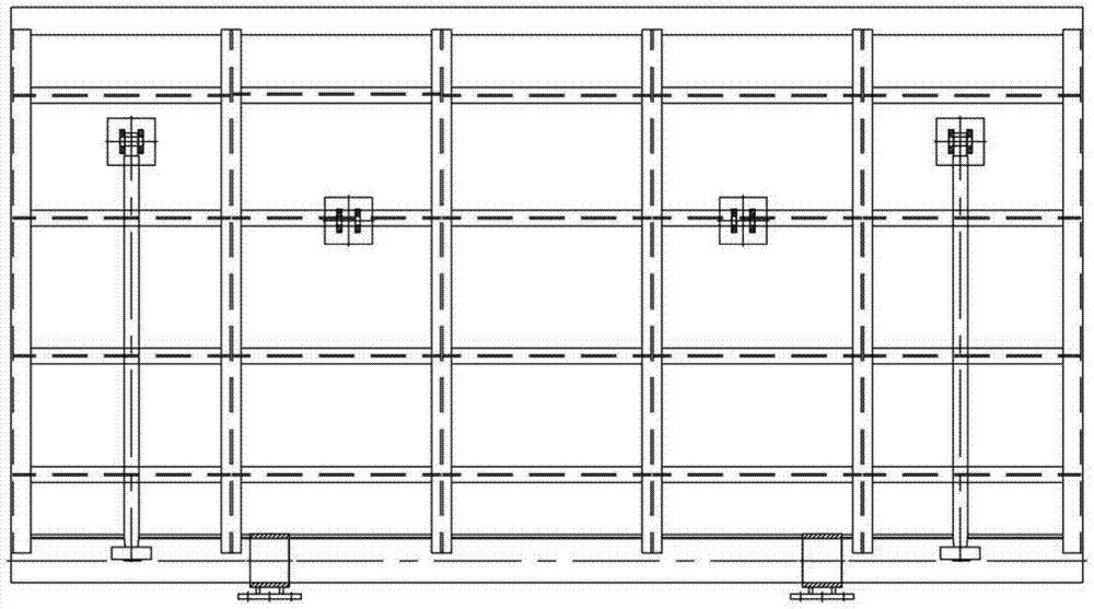
[0056] The telescopic cylinder is installed in the gap between the longitudinal and horizontal beams of the arc cavity in the dam body.

[0057] Two sets of upper hinge supports are fixedly arranged on the dam body, and the upper ends of the support rods are hinged on one set of upper hinge supports. Another group of upper hinge supports is used for installing the main hydraulic cylinder, and the main hydraulic cylinder is used to push the dam body to turn over.

[0058] It also includes a support platform for ...

Embodiment 2

[0088] The above-mentioned method of using the hydraulic dam of the built-in drive support mechanism includes the following steps:

[0089] 1) In the initial state, the dam body is lodging on the support platform; the support rods are received in the dam body;

[0090] 2) When the dam body is lifted, the support rod rises with the dam body;

[0091] 3) When the dam body rises to the specified height, start the telescopic cylinder to make the piston rod contract, the lower end of the support rod opens away from the dam body, falls on the steps of the support platform, and the dam body reaches the first height;

[0092] 4) The piston rod of the telescopic cylinder stretches out, the lower end of the support rod moves towards the direction of the dam body, and falls on the foundation plane of the lower part of the supporting platform, and the dam body reaches the second height;

[0093] 5) When the dam needs to be lowered, start the telescopic cylinder to extend the piston rod, ...


PUM


Abstract

The invention discloses a hydraulic dam with a built-in drive support mechanism and a method for using the same. It comprises: a dam body; a telescopic cylinder installed along the height direction of the dam body; The piston rod of the cylinder is hinged; the support rod used to support the dam body, the upper end of the support rod is fixedly connected with the second end of the connecting rod arm, and the telescopic cylinder is installed in the gap between the vertical and horizontal beams of the arc cavity in the dam body, free from water erosion and sediment Pollution, improve service life and reduce failure rate.

Description

technical field [0001] The invention belongs to the technical field of water conservancy engineering, and in particular relates to a hydraulic dam with a built-in driving support mechanism and a using method thereof. Background technique [0002] Conventional strut-driven cylinders are installed in foundation pits. [0003] In the process of realizing the present invention, the inventors found that the prior art has at least the following problems: the driving oil cylinder has been silted up by sediment for a long time, resulting in heavy pollution, strong corrosion and high failure rate. Traditional support rods need to be equipped with sliding guide grooves, reserved foundation pits, and secondary pouring of embedded parts. The construction cost is high and the process is complicated. The traditional support rods cannot be lifted to discharge the dam when the power is lost. When the flood surges and the power is lost, the dam cannot be released in time to discharge the fl...

Claims


Application Information

Patent Timeline
Patent Type & Authority Patents(China)
IPC IPC(8): E02B7/44
Inventor 张开会张火生赵毅汪玉平汪永辉魏琴琴
Owner WUHU YINHONG HYDRAULIC COMPONENTS
Why Eureka
Try Eureka