Roof counterweighted communications tower

A technology for communication poles and towers, which is applied in the direction of roofs, roof coverings, towers, etc. It can solve the problems of weak position adjustment ability of communication poles and towers, damage to the roof waterproof layer, and water leakage in houses, so as to increase the number of mounted antennas and increase the load space and load capacity, the effect of avoiding damage

Active Publication Date: 2015-12-16
HUAXIN CONSULTATING CO LTD
View PDF8 Cites 33 Cited by
  • Summary
  • Abstract
  • Description
  • Claims
  • Application Information

AI Technical Summary

Problems solved by technology

[0002] It is often necessary to set up communication towers on the roof (roof) to support various equipment and antennas. The new communication towers on the roof usually use expansion bolts and other connection structures to fix the communication antenna brackets (communication towers) to the roof structure layer. Although this method It

Method used


Image

  • Roof counterweighted communications tower
  • Roof counterweighted communications tower
  • Roof counterweighted communications tower

Examples


Embodiment 1

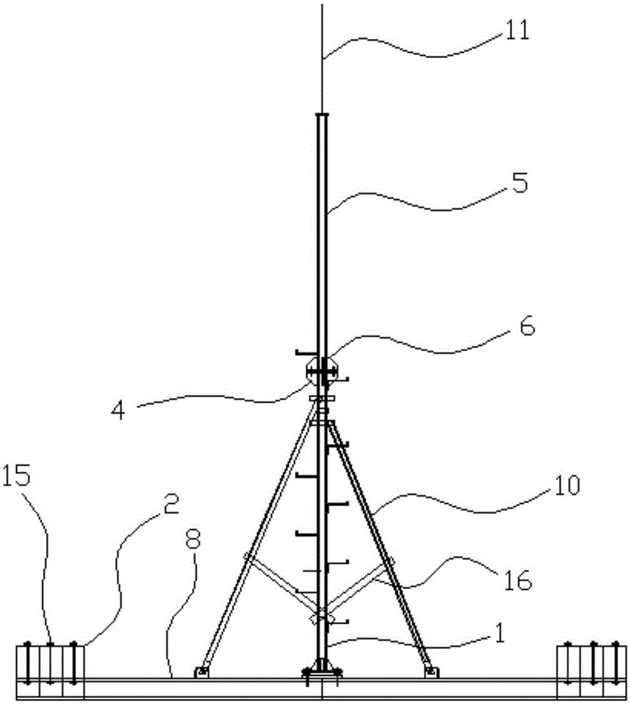
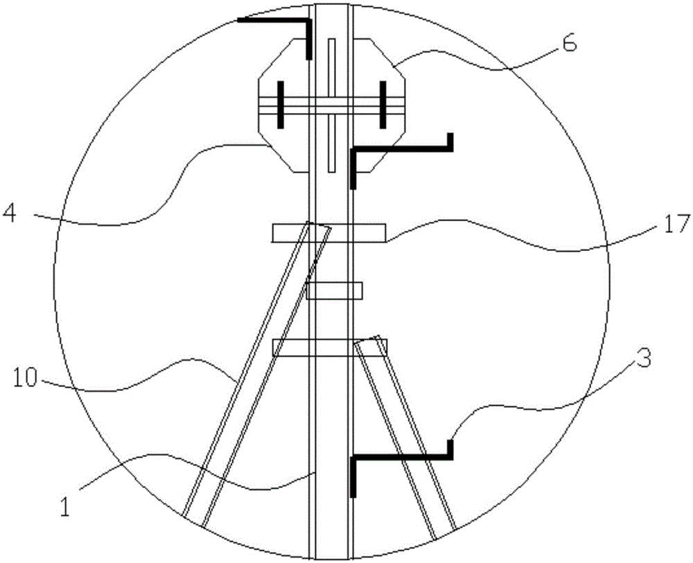
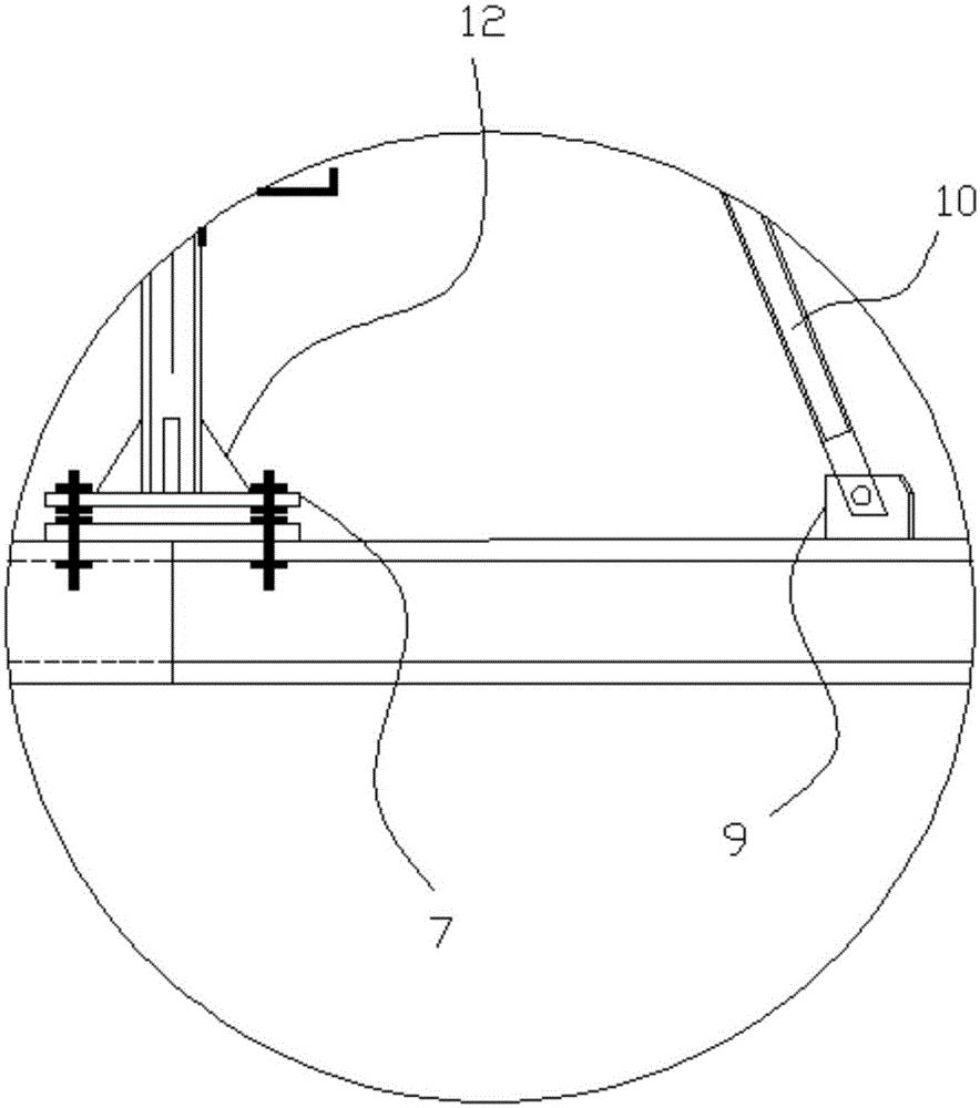
[0027] Embodiment 1: as Figure 1 to Figure 5In the illustrated embodiment, a roof counterweight communication tower includes at least one tower main pole 1 and several prefabricated concrete counterweights 2. The main pole of the tower is provided with several climbing nails 3. The tower The top of the main pole is provided with a top flange 4, the top of the main pole of the tower is provided with a steel pipe 5, the bottom of the steel pipe is provided with a bottom flange 6, and the top flange of the pole is docked with the bottom flange of the pipe. A main flange 7 is provided at the bottom of the main pole of the pole tower, and a corresponding bottom steel beam 8 is provided on the described prefabricated concrete counterweight, and the bottom steel beam is connected with the main flange, and the bottom steel beam The beam is provided with a fixed support base 9, the fixed support base is provided with a fixed support rod 10, and the main pole of the tower is provided w...

Embodiment 2

[0032] Embodiment 2: the basic structure and implementation mode of this embodiment are the same as embodiment 1, and its difference is, as Figure 7 to Figure 10 As shown in, it also includes a trigger cylinder 18, a pullback protection cylinder 19, a bottom steel beam is provided with a fixed platform 20, the trigger cylinder is fixedly connected with the fixed platform, and the top wall of the trigger cylinder is provided with There is a threading hole 21, the main rod of the pole tower is provided with a trigger cable 22, and the trigger cylinder is provided with a trigger piston 23 slidingly connected with the trigger cylinder, the sliding direction is the up and down direction, and the trigger cable One end is connected to the main pole of the pole tower, the other end is connected to the trigger piston, the trigger cable passes through the cable hole, the trigger piston is at the bottom of the trigger cylinder, at least one limit spring 24 is arranged in the trigger cyli...


PUM


Abstract

The invention discloses a roof counterweighted communications tower and aims to provide a communications tower installable without damaging a roof waterproof layer, quick to install, firm to position, and convenient to mount and demount and dislocate. The tower comprises a tower main pole and a plurality of precast concrete counterweights; a pole-top flange is disposed at the top of the tower main pole; a steel pipe is disposed above the tower main pole; a pipe-bottom flange is disposed at the bottom of the steel pipe; the pole-top flange is abutted to the pipe-bottom flange; a main flange is disposed at the bottom of the tower main pole; the precast concrete counterweights are provided with bottom steel beams; the bottom steel beams are provided with fixed support bases; fixed support rods are disposed on the fixed support bases; the tower main pole is provided with a plurality of support clamps connected with corresponding support rods. The roof counterweighted communications tower has the advantages that the tower is self-erected on a roof through the counterweights so that damage to the roof waterproof layer caused by bolt structures is avoided; extension holes are provided to enable higher extensibility, and adding counterweights at corresponding positions is required only when new antennas are added.

Description

technical field [0001] The invention belongs to the technical field of roof communication towers, in particular to a roof counterweight communication tower. Background technique [0002] It is often necessary to set up communication towers on the roof (roof) to support various equipment and antennas. The new communication towers on the roof usually use expansion bolts and other connection structures to fix the communication antenna brackets (communication towers) to the roof structure layer. Although this method It can realize the setting and positioning of communication towers, but it will also damage the waterproof layer of the roof, which is easy to cause unfavorable phenomena such as water leakage in the house, and this method is relatively inconvenient to disassemble and assemble, and the position adjustment ability of communication towers is also weak. Contents of the invention [0003] The present invention aims to overcome the deficiencies in the prior art, and pro...

Claims


Application Information

Patent Timeline
IPC IPC(8): E04H12/00E04H12/22E04D13/00
Inventor 姚云龙竹影张珩章跃军田大年曾晓任高杰卢梭盛佳苏鹤善
Owner HUAXIN CONSULTATING CO LTD
Why Eureka
Try Eureka