Constant-temperature faucet achieving double-path water output

A faucet and constant temperature technology, which is applied in the field of bathroom faucets, can solve the problems of reduced service life of ceramic valve core, influence of ceramic sheet sealing life, accelerated aging and variation of shell, etc., to reduce the number of sealing channels, convenient positioning, and easy mold making. Effect

Inactive Publication Date: 2015-12-16
TAIZHOU GUOREN TEMPERATURE CONTROL SANITARY WARE TECH CO LTD
View PDF8 Cites 14 Cited by
  • Summary
  • Abstract
  • Description
  • Claims
  • Application Information

AI Technical Summary

Problems solved by technology

[0009] 3. The assembly is difficult. When the valve body is installed, the sealing ring on the outer circle of the ceramic valve core is an interference and tight fit, so it will cause friction with the inside of the faucet body. It is difficult to control the alignment of the bottom positioning feet.
This will result in low assembly efficiency and correspondingly high manufacturing costs
[0010] 4. One water enters from the side, and the side of the ceramic sheet is constantly under water pressure, causing uneven force on the ceramic sheet, which may affect the sealing life of the ceramic sheet
[0011] 5. When the ceramic valve in the faucet is in use, its shell is in the state of being soaked in water for a long time. The temperature of the water, the acid-base salt in the water and other substances, the physical and chemical factors of these waters will accelerate the aging of the shell, resulting in the use of the ceramic valve core. Reduced lifespan
[0013] Another example is the hot and cold water synchronous switch thermostatic mixing faucet disclosed in the Chinese invention patent, the application number is: 201220598371.0, and th

Method used


Image

  • Constant-temperature faucet achieving double-path water output
  • Constant-temperature faucet achieving double-path water output
  • Constant-temperature faucet achieving double-path water output

Examples


Embodiment Construction

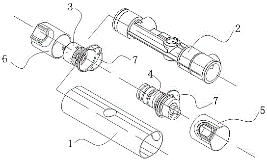
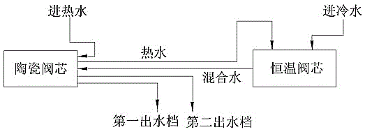
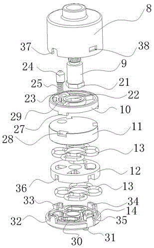
[0060] The embodiment of the present invention provides a dual-way water outlet thermostatic faucet, which cancels the water inlet and outlet holes on the side of the valve core shell of the ceramic valve core, and instead sets the water inlet and outlet holes at the bottom, realizing two levels. The water outlet function reduces the difficulty of processing, facilitates positioning and installation, slows down wear and aging, and improves service life.

[0061] The following will clearly and completely describe the technical solutions in the embodiments of the present invention with reference to the accompanying drawings in the embodiments of the present invention. Obviously, the described embodiments are only some, not all, embodiments of the present invention. Based on the embodiments of the present invention, all other embodiments obtained by persons of ordinary skill in the art without creative efforts fall within the protection scope of the present invention.

[0062] se...


PUM


Abstract

The embodiment of the invention discloses a constant-temperature faucet achieving double-path water output. The constant-temperature faucet comprises a shell, a main valve body, a ceramic valve element, a constant-temperature valve element, a hand wheel constant-temperature assembly, a hand wheel quick opening assembly and a shell side cover. The ceramic valve element comprises a valve element shell, an adjusting handle, a drive plate, a moving sheet, a static sheet, a sealing piece and a base from top to bottom. The static sheet is provided with a hot water inlet, a hot water outlet, a mixed water inlet, a first gear water outlet and a second gear water outlet which are connected with pipelines. Three flow guide channels are arranged on the moving sheet, and the flow guide channels of the moving sheet are driven by rotating the adjusting handle of the ceramic valve element through the hand wheel quick opening assembly to match the static sheet to form a water output closing state or a first gear water output state or a second gear water output state. According to the constant-temperature faucet achieving double-path water output, processing difficulty is lowered, locating and mounting are convenient, wearing and ageing slow down, and the service life is prolonged.

Description

technical field [0001] The invention relates to the technical field of bathroom faucets, in particular to a constant temperature water faucet with two-way water outlets. Background technique [0002] The thermostatic faucet is a commonly used water flow control device in the bathroom. In order to facilitate the shower and meet the user's spray preferences, the bathroom is often equipped with a top-mounted shower head and a hand-held shower head, so that It is required that the thermostatic faucet has the function of two-way water outlet. The existing thermostatic faucet capable of realizing two-way water outlets has the following two schemes. [0003] The first solution: the ceramic valve core has 3 holes, one hole enters the mixed water inlet hole of mixed water, and the other two holes respectively output two mixed water outlet holes; hot water and cold water respectively enter the constant temperature of the constant temperature faucet The spool, after being mixed into ...

Claims


Application Information

Patent Timeline
IPC IPC(8): F16K11/20F16K31/60F16K37/00
CPCF16K11/207F16K31/607F16K37/0008
Inventor 杨和军
Owner TAIZHOU GUOREN TEMPERATURE CONTROL SANITARY WARE TECH CO LTD
Why Eureka
Try Eureka