
Double speed motor with forced circulation

A technology of motor and fluid pressure, applied in the direction of servo motor, remote control motor, servo motor assembly, etc., can solve the problem of unexpected rotation of the vehicle

Inactive Publication Date: 2005-01-12
EATON CORP
View PDF2 Cites 0 Cited by
  • Summary
  • Abstract
  • Description
  • Claims
  • Application Information

AI Technical Summary

Problems solved by technology

However, if there is a delay between the shifting of one motor and the shifting of the other, the result is one motor running at high rpm and the other at low rpm, causing the vehicle to turn unexpectedly

Method used


Image

  • Double speed motor with forced circulation
  • Double speed motor with forced circulation
  • Double speed motor with forced circulation

Examples


Embodiment Construction

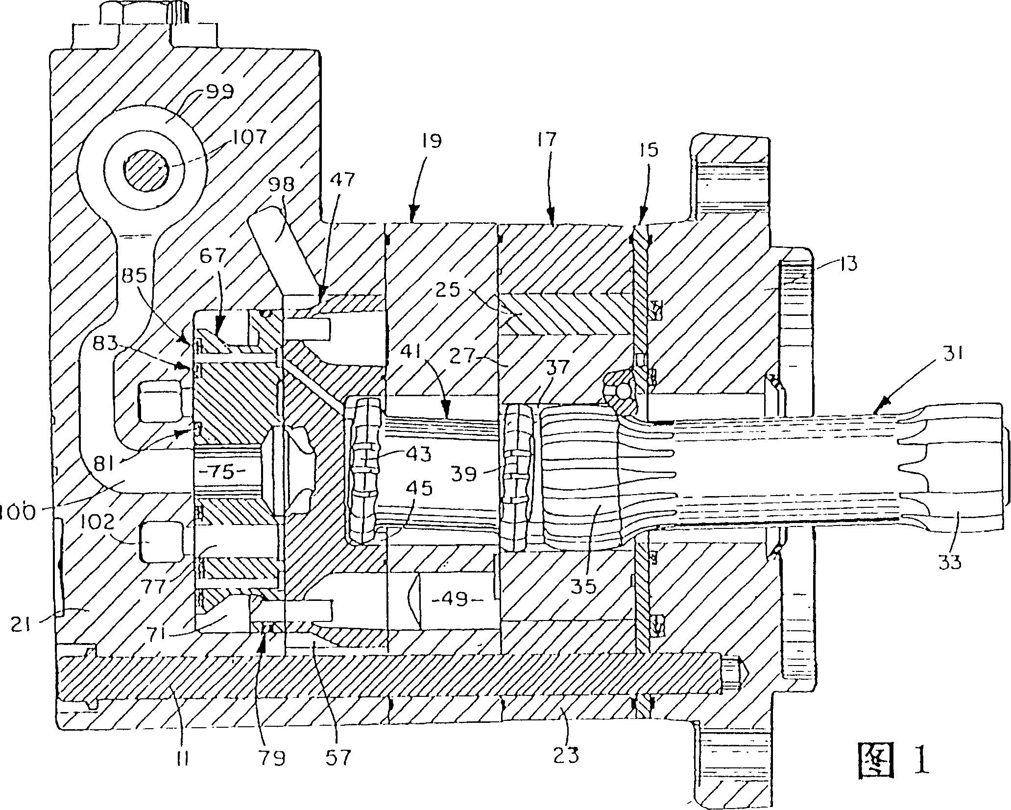
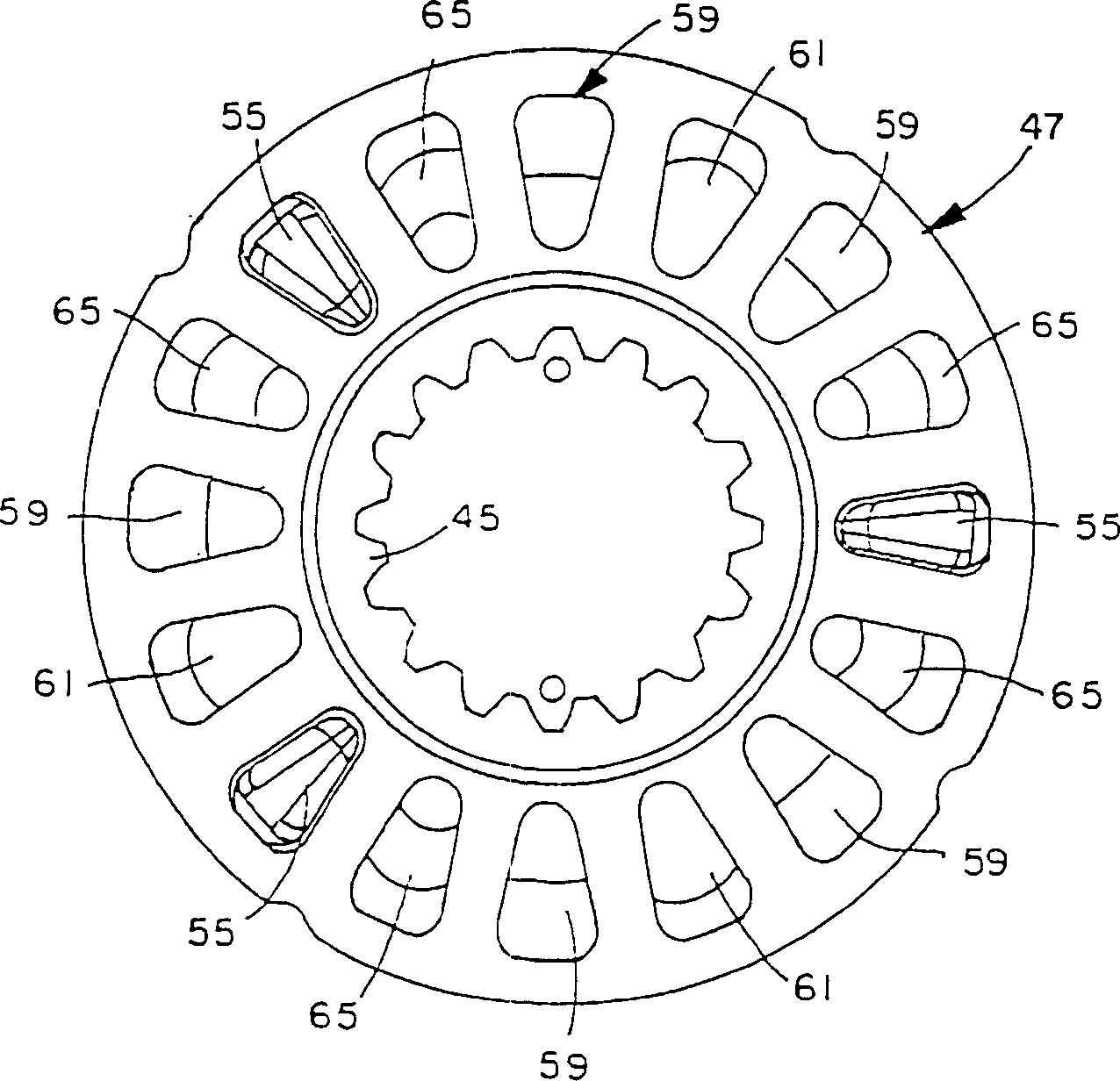
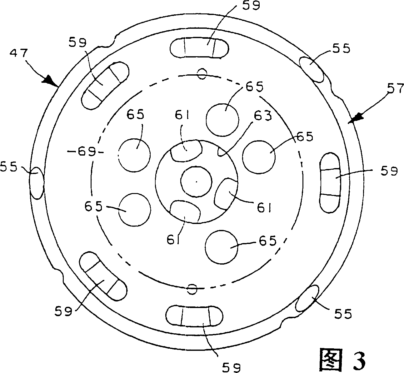
[0026] Referring now to the accompanying drawings, the accompanying drawings are not intended to limit the present invention, Figure 1 is an axial sectional view of a rotary motor applicable to the present invention, which is described and illustrated in more detail in U.S. Patent No. 3,572,983, This patent is incorporated by reference in this specification. More specifically, the swing motor shown in FIG. 1 is a rotating disk, two-speed type, described and illustrated in more detail in the aforementioned US Patent No. 4,480,971. When applied to a device of the kind shown here, the term "motor" shall obviously also include such a device used as a pump.

[0027] The rotary motor shown in Fig. 1 comprises a plurality of parts fastened together eg by a plurality of bolts 11 (only one of which is shown in Fig. 1). The motor includes a front flange member 13 , a wear plate 15 , a gerotor displacement mechanism 17 , an orifice or stationary valve means 19 and a valve housing portio...


PUM


Abstract

A two speed gerotor motor in which the rotary disk valve (47) and the balancing ring (67) cooperate with a control valve assembly (87) to define four different fluid zones arranged within a housing (21) in a generally concentric pattern to provide a relatively compact arrangement. Among the four fluid zones one (95) is always connected to an inlet (51) while another (101) is always connected to an outlet (53). The middle two zones (97, 99) communicate with each other in the high speed, low torque mode. Operatively associated with the control valve assembly (87) is a shuttle valve (103) such that high pressure is always communicated to the middle two zones, such that high pressure is always circulated within the gerotor gear set (17) in the high speed, low torque mode. The control valve (87) includes a spool valve (107) including dampening passages (123, 125, 127) which dampen or cushion the shifting of the spool valve between the high speed and low speed conditions.

Description

technical field [0001] This invention relates to rotary fluid pressure devices in which a rotary gear set is used as the fluid displacement mechanism, and more particularly to such devices having a two-speed capability. [0002] While the teachings of the present invention are applicable to devices having non-rotary fluid displacement mechanisms, such as cam lobe devices, the invention is particularly applicable to rotary devices and will be described in connection with rotary devices. Background technique [0003] Devices utilizing rotary gear wheel sets are used in a variety of applications, the most common being the use of such devices as low speed, high torque motors. A common application for low-speed, high-torque motors is in propulsion vehicles, where the vehicle includes an engine-driven pump that supplies pressurized fluid to a pair of rotary motors, each of which cooperates with one of the drive wheels. Those skilled in the art understand that many swing motors ut...

Claims


Application Information

Patent Timeline
Patent Type & Authority Patents(China)
IPC IPC(8): F03C2/08F01C1/02F04C2/00F04C2/10F04C14/08
CPCF04C14/08F04C2/105F04C2/00F01C1/02F03C2/08
Inventor 唐纳德·M·霍斯塔卡伦·J·雷德福德怀特·B·斯蒂芬森
Owner EATON CORP
Learn More