Air conditioner exhausting device

An air-conditioning and cold air technology, applied in the field of air-conditioning exhaust devices, to achieve the effect of improving efficiency and comfort

Inactive Publication Date: 2015-12-16
JIANGXI NORMAL UNIVERSITY
View PDF5 Cites 3 Cited by
  • Summary
  • Abstract
  • Description
  • Claims
  • Application Information

AI Technical Summary

Problems solved by technology

[0005] The purpose of the present invention is to provide a device that can make the air conditioner evenly output the air and keep the indoor temperature in view of the deficiency of the existing exhaust window.

Method used


Image

  • Air conditioner exhausting device
  • Air conditioner exhausting device
  • Air conditioner exhausting device

Examples


Embodiment Construction

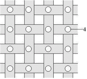
[0017] The structure of the device of the present invention includes: air conditioner, cold air main outlet, cold air conveying pipe, cold air outlet, hot air main outlet, hot air conveying pipe, cold air outlet;

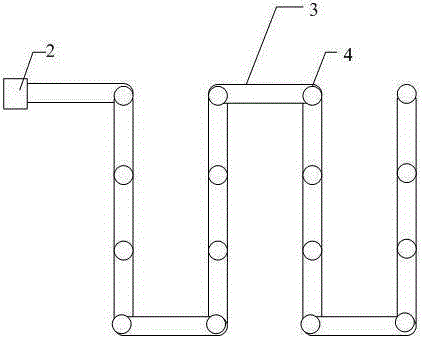
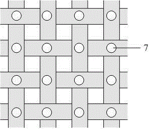
[0018] The device of the present invention is connected in the following way: the cold and hot air outlets of the air conditioner are separated, the main outlet of the cold air is on the top, and the main outlet of the hot air is on the bottom; the main outlet of the cold air is connected with the cold air delivery pipeline; the main outlet of the hot air is connected with the hot air delivery pipeline; The cold air delivery pipe is laid horizontally in an S shape along the top of the house; the hot air delivery pipe is laid horizontally in an S shape along the bottom of the house; the cold air outlets are evenly distributed on the cold air delivery pipe; the hot air outlets are evenly distributed on the hot air delivery pipe.

[0019] The device operates like this: ...


PUM


Abstract

An air conditioner exhausting device comprises an air conditioner, a cold air main outlet, a cold air conveying pipeline, cold air outlets, a hot air main outlet, a hot air conveying pipeline and hot air outlets. The cold air outlets and the hot air outlets of the air conditioner are separated, the cold air main outlet is located in the upper portion, and the hot air main outlet is located in the lower portion. The cold air main outlet is connected with the cold air conveying pipeline. The hot air main outlet is connected with the hot air conveying pipeline. The cold air conveying pipeline is laid on a room in the shape of S. The hot air conveying pipeline is horizontally laid on the lower portion of the room in the shape of S. The cold air outlets are evenly distributed in the cold air conveying pipeline. The hot air outlets are evenly distributed in the hot air conveying pipe. The air conditioner exhausting device can evenly convey air conditioner air to each corner of the room, the indoor temperature is constant, and the using efficiency and the comfort degree of the air conditioner are greatly improved.

Description

technical field [0001] The invention relates to an air-conditioning exhaust device, which belongs to the field of electronic equipment. Background technique [0002] With the continuous development of the economy, air conditioners are widely used in people's daily work and life, and have become an indispensable electrical appliance in public places or families. The structure of traditional air-conditioning exhaust windows is roughly the same. Most of the air outlets are in the shape of rectangular strips. Generally, the fan blades are used to swing left and right to adjust the air-conditioning air direction. This type of exhaust window can only exhaust air in one direction, which is relatively On the basis of the above, the new air-conditioning exhaust window adds up and down swinging wind blades, which can exhaust air in two directions, but the size of the air outlet cannot be adjusted, the air-conditioning exhaust effect is not ideal, and the comfort is also poor. [0003...

Claims


Application Information

Patent Timeline
IPC IPC(8): F24F13/06
CPCF24F13/06F24F2013/0608
Inventor 张光河刘芳华
Owner JIANGXI NORMAL UNIVERSITY
Why Eureka
Try Eureka