Method and device for image prediction

A technology for predicting direction and image, applied in image communication, digital video signal modification, electrical components and other directions, which can solve the problems of unable to improve coding efficiency, unable to guarantee the accuracy of motion vector information of adjacent blocks, etc.

Active Publication Date: 2015-12-16
HUAWEI TECH CO LTD +1
View PDF2 Cites 118 Cited by
  • Summary
  • Abstract
  • Description
  • Claims
  • Application Information

AI Technical Summary

Problems solved by technology

Such a method requires that the accuracy of the motion vector information of the adjacent blocks multiplexed by the current block is high, and the existing technology cannot guarantee the accuracy of the motion vector information of the adjacent blocks, so that the coding efficiency cannot be improved.

Method used


Image

  • Method and device for image prediction
  • Method and device for image prediction
  • Method and device for image prediction

Examples


Embodiment approach 1210

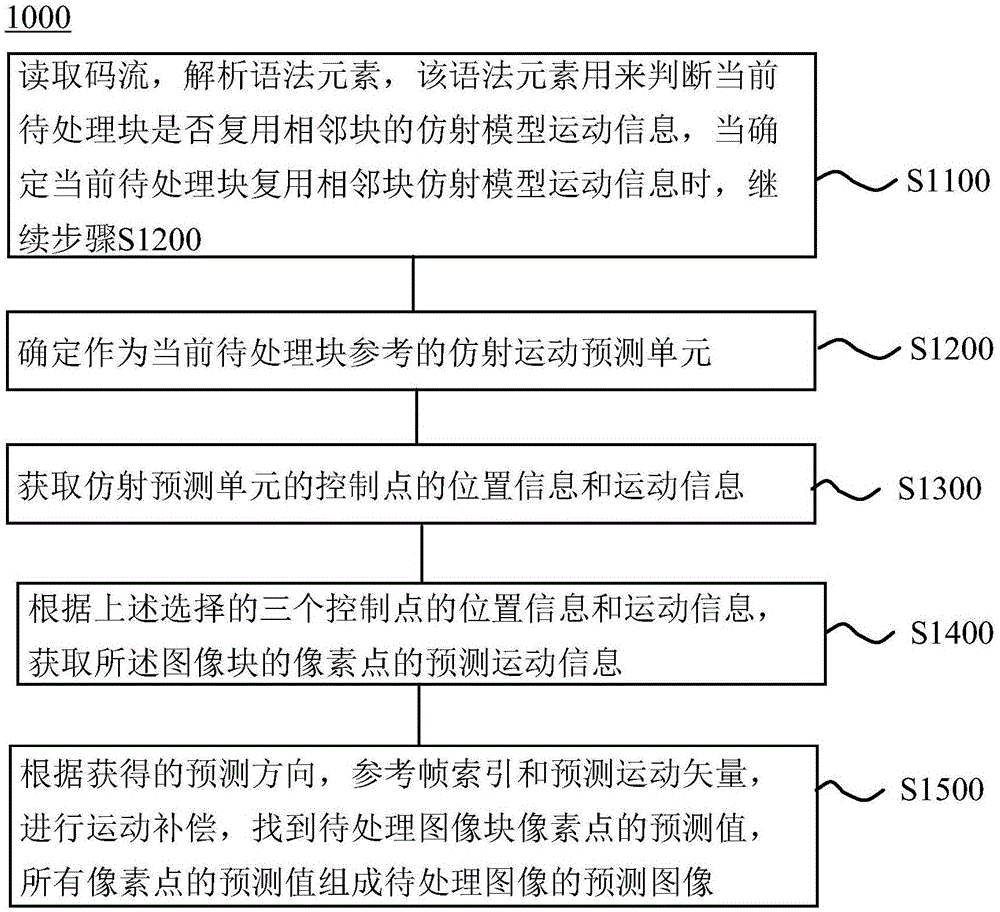
[0144] The first specific implementation method 1210 of this step includes:

[0145] S1211: Determine a set of candidate prediction units of the current block to be processed.

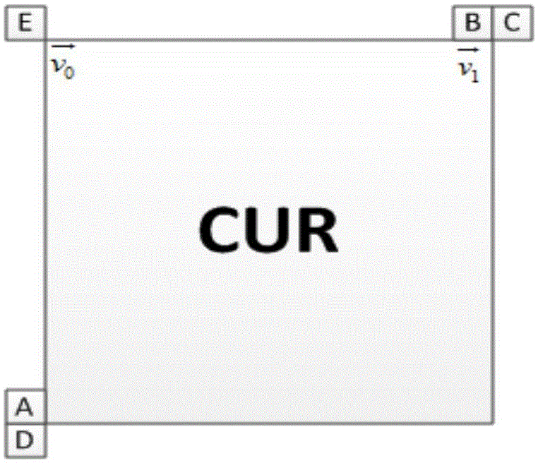
[0146] Such as figure 2 As shown, in the embodiment of the present invention, the prediction units where the 4x4 blocks at the five positions A, B, C, D, and E are adjacent to each other in space of the current block to be processed are selected to form a set. It should be understood that A, B, C can also be selected For several positions in D, E, the prediction units where other time-domain neighboring blocks are located can also be selected to form a set, which is not limited.

[0147] S1212: Check whether the prediction unit in the set is an affine motion prediction unit in a preset order.

[0148] Among them, the preset sequence is the sequence predetermined by the encoding and decoding ends through protocols and the encoding and decoding ends are consistent. In the embodiment of the present invention, th...

Embodiment approach 1220

[0150] The second specific implementation method 1220 of this step includes:

[0151] S1221: Determine a set of candidate prediction units of the current block to be processed.

[0152] In addition to the same set determination method as S1211, it may also include moving the non-affine prediction unit blocks in the above set out of the set. For example, the set determined by the determination method of S1211 is the prediction where A, B, C, D, and E are located. If the prediction unit where C and D are located is not an affine prediction unit, then C and D are removed from the set, and the determined candidate prediction unit set is the prediction unit where A, B, and E are located.

[0153] It can also include limiting the capacity of the set and removing candidate prediction units whose check order is outside the allowable number out of the set, for example, limiting the set to a maximum of 2 candidate prediction units, the set determined by the determination method of S1211 and th...

Embodiment approach 1310

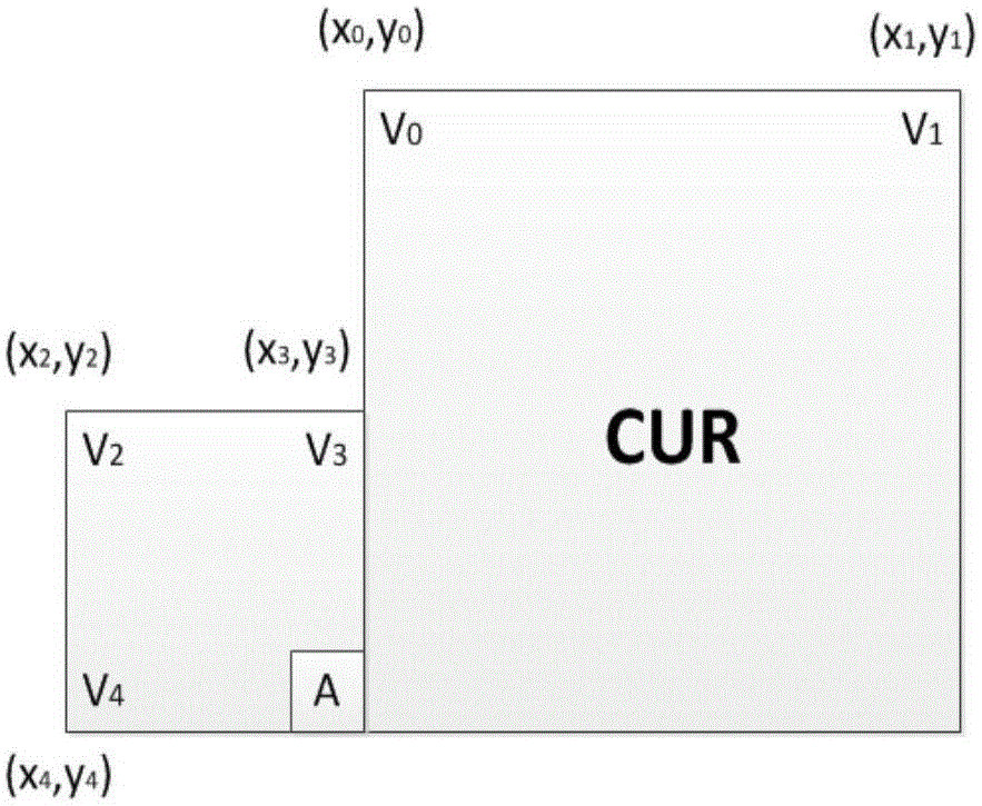
[0159] The first specific implementation method 1310 of this step includes: randomly selecting three control points from the four control points of the affine prediction unit, and obtaining their position information, motion vector information, prediction direction and reference frame index. All pixels of the same affine prediction unit have the same prediction direction and reference frame index, so the prediction direction and reference frame index of all control points are also the same.


PUM


Abstract

The invention provides a method and a device for image prediction. The method comprises the steps of: obtaining a first reference unit of an image unit, wherein the image unit and the first reference unit obtain respective predicted images by using the same affine model; obtaining motion information of basic motion compensation units at the at least two preset positions of the first reference unit; and obtaining the motion information of the basic motion compensation units of the image unit. Therefore, by multiplexing the motion information of the first reference unit which adopts the same affine pre-model, a motion vector of the current image unit is obtained more exactly, the coding and decoding complexity is kept while the prediction accuracy is improved, and the coding and decoding performance is improved.

Description

Technical field [0001] The present invention relates to the field of video image processing, in particular to a method and equipment for image prediction. Background technique [0002] With the rapid development of Internet technology and the increasing enrichment of people’s material and spiritual culture, there are more and more demand for video applications on the Internet, especially for high-definition video applications, and the amount of data in high-definition video is very large. To be able to transmit on the Internet with limited bandwidth, the first problem that must be solved is the problem of high-definition video compression coding. At present, there are two international organizations specializing in the formulation of video coding standards, namely, the International Organization for Standardization (ISO") / International Electrotechnical Commission (International Electrotechnical Commission, "IEC"). (MotionPictureExpertsGroup, referred to as "MPEG") and Video Codi...

Claims


Application Information

Patent Timeline
Patent Type & Authority Applications(China)
IPC IPC(8): H04N19/105H04N19/50
CPCH04N19/176H04N19/527H04N19/54H04N19/105H04N19/573H04N19/51H04N19/139H04N19/172H04N19/52
Inventor 吕卓逸李礼李厚强杨海涛
Owner HUAWEI TECH CO LTD
Why Eureka
Try Eureka