Automatic material collection device

A material and automatic technology, applied in the stacking, transportation and packaging of objects, can solve the problems of large limitations, work intensity, high efficiency and cost, and achieve the effect of improving work efficiency and reducing production costs.

Active Publication Date: 2015-12-23
QINGDAO SAWOTE ROBOT CO LTD
View PDF6 Cites 0 Cited by
  • Summary
  • Abstract
  • Description
  • Claims
  • Application Information

AI Technical Summary

Problems solved by technology

At present, the collection of materials is manually sorted out, and there is no set of automatic equipment for this operation. Although it can be operated, it increases the intensity of human work, low efficiency, high cost, and large limitations.

Method used


Image

  • Automatic material collection device
  • Automatic material collection device

Examples


Embodiment 1

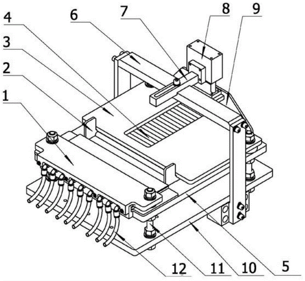
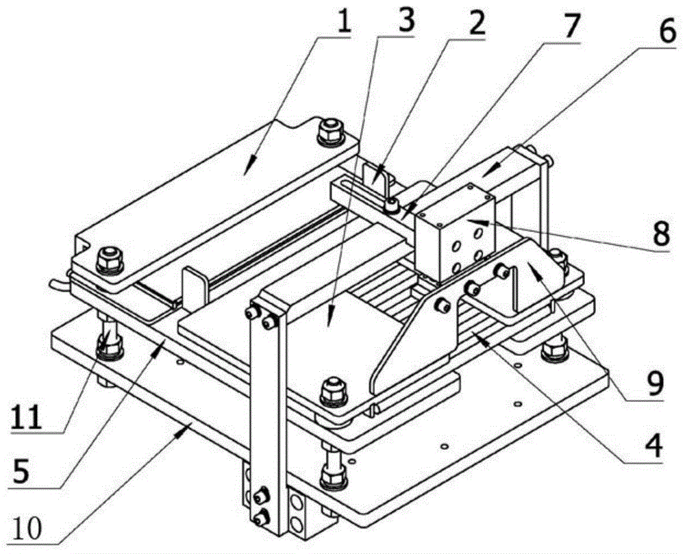
[0021] Such as figure 1 , figure 2 As shown, an automatic material collecting device includes an air blowing mechanism and a collecting mechanism. The collecting mechanism is provided with a cavity 4 for materials to pass through, and the blowing mechanism communicates with one end of the cavity 4 through the collecting channel. Among them, the air blowing mechanism includes an air outlet 1 and an air source, and the air outlet 1 communicates with the air source through an air pipe 12; Arranged in parallel up and down, a cavity 4 is formed between the upper bottom plate 5 , the upper cover plate 3 and the two side plates, and the other end of the cavity 4 is provided with a baffle plate 9 . The bottom of the air outlet 1 is fixed on the upper base plate 5, and the collection channel is formed between the air outlet 1, the upper base plate 5 and the collection mechanism cavity 4, and the restriction plates 2 are arranged on both sides of the collection channel.

Embodiment 2

[0023] Such as figure 1 , figure 2 As shown, an automatic material collecting device is mainly used for collecting tubular objects or columns, including an air blowing mechanism and a collecting mechanism. The collecting mechanism is provided with a cavity 4 for materials to pass through, and the blowing mechanism passes through The collection channel communicates with one end of the cavity 4 . Among them, the air blowing mechanism includes an air outlet 1 and an air source, and the air outlet 1 communicates with the air source through an air pipe 12; Arranged in parallel up and down, a cavity 4 is formed between the upper bottom plate 5, the upper cover plate 3 and the two side plates. The upper cover plate 3 is provided with a transparent glass window. The bottom of the air outlet 1 is fixed on the upper base plate 5, and the collecting channel is formed between the air outlet 1, the upper base plate 5 and the collecting mechanism cavity 4, and the restricting plates 2 a...


PUM


Abstract

The invention belongs to the field of automatic machines, and particularly relates to an automatic material collection device. The automatic material collection device is created for liberating the labor force and improving the working efficiency. The automatic material collection device comprises an air blowing mechanism and a collecting mechanism, the collecting mechanism is provided with a cavity for materials to pass through, and the air blowing mechanism is communicated with one end of the cavity through a collecting channel. Manpower can be replaced with the device, neatening can be efficiently carried out according to requirements, and the production cost is reduced.

Description

technical field [0001] The invention belongs to the field of automatic mechanical equipment, and in particular relates to an automatic material collecting device. Background technique [0002] In the high-speed automatic production process of materials, especially tubular objects or columns, the front-end processing is completed, and the spacing and order of the materials on the subsequent processing device are usually uncertain. In order to facilitate the subsequent automatic batch processing of materials, we Materials need to be collected to facilitate subsequent further processing operations. At present, the collection of materials is done manually, and there is no set of automatic equipment for this operation. Although it can be operated, it increases the intensity of human work, low efficiency, high cost, and large limitations. Based on this, the present invention provides a solution to this problem. Contents of the invention [0003] In order to liberate the labor ...

Claims


Application Information

Patent Timeline
Patent Type & Authority Applications(China)
IPC IPC(8): B65G57/18
Inventor 李泽伟
Owner QINGDAO SAWOTE ROBOT CO LTD
Why Eureka
Try Eureka