Intelligent fire extinguisher cabinet and working method thereof

A technology for fire extinguisher boxes and fire extinguishers, which is applied to electric fire alarms, fire alarms that rely on smoke/gas effects, and instruments to achieve the effects of collection, difficulty, and stability

Pending Publication Date: 2021-04-06
卢冠军 +1
View PDF13 Cites 0 Cited by
  • Summary
  • Abstract
  • Description
  • Claims
  • Application Information

AI Technical Summary

Problems solved by technology

However, although there is no technical difficulty in building an electronic scale in the fire extinguisher box, some new technical problems will follow

Method used


Image

  • Intelligent fire extinguisher cabinet and working method thereof
  • Intelligent fire extinguisher cabinet and working method thereof
  • Intelligent fire extinguisher cabinet and working method thereof

Examples


Embodiment 1

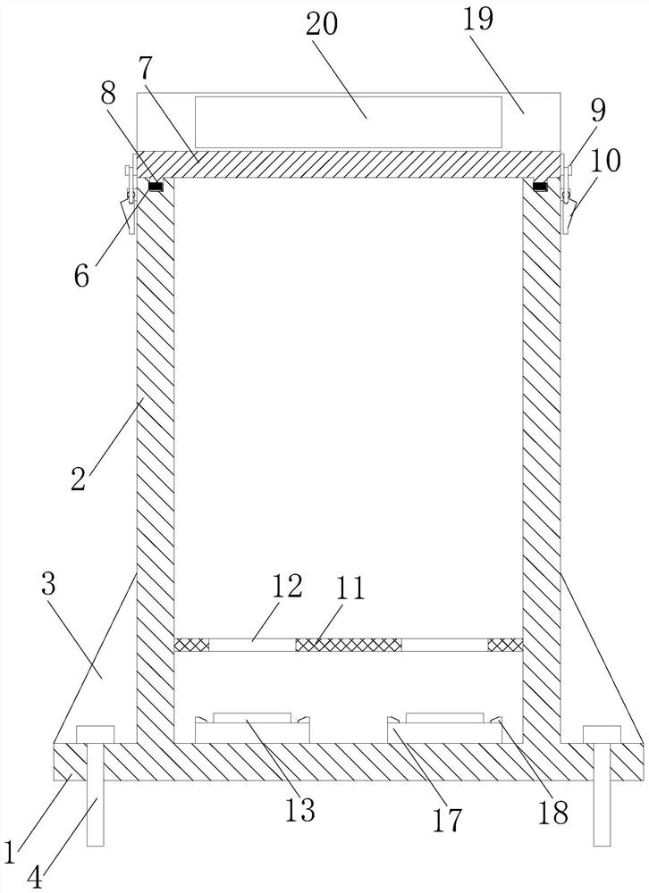
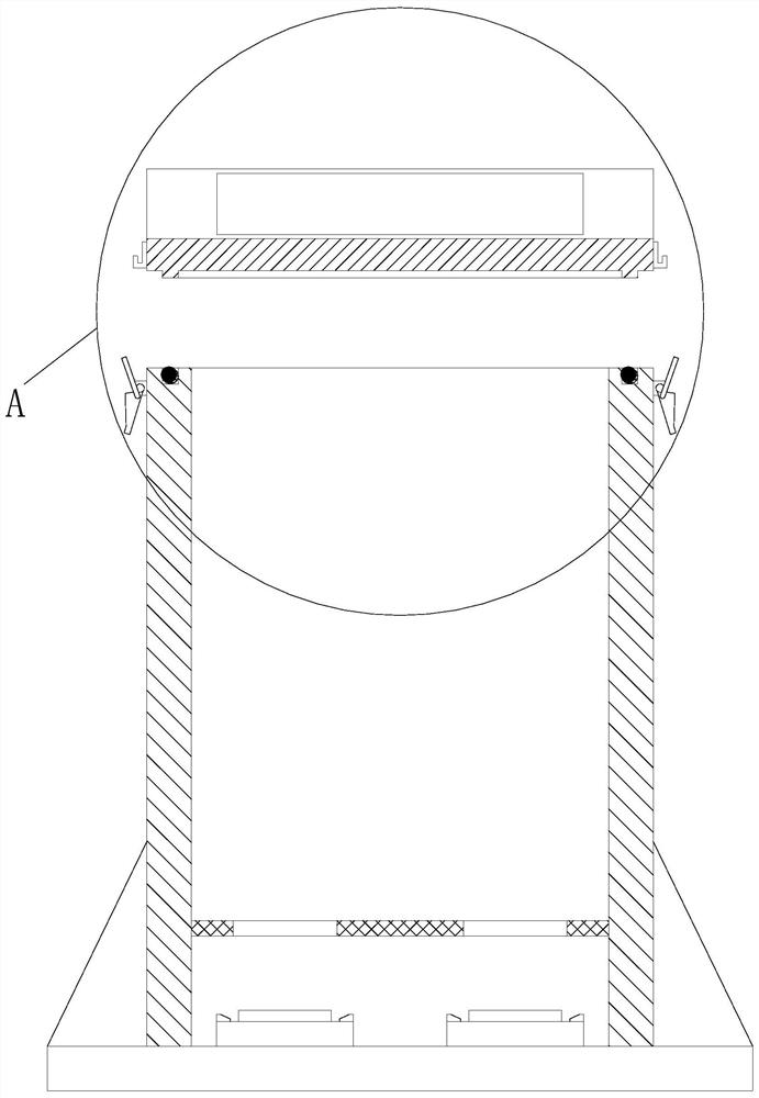
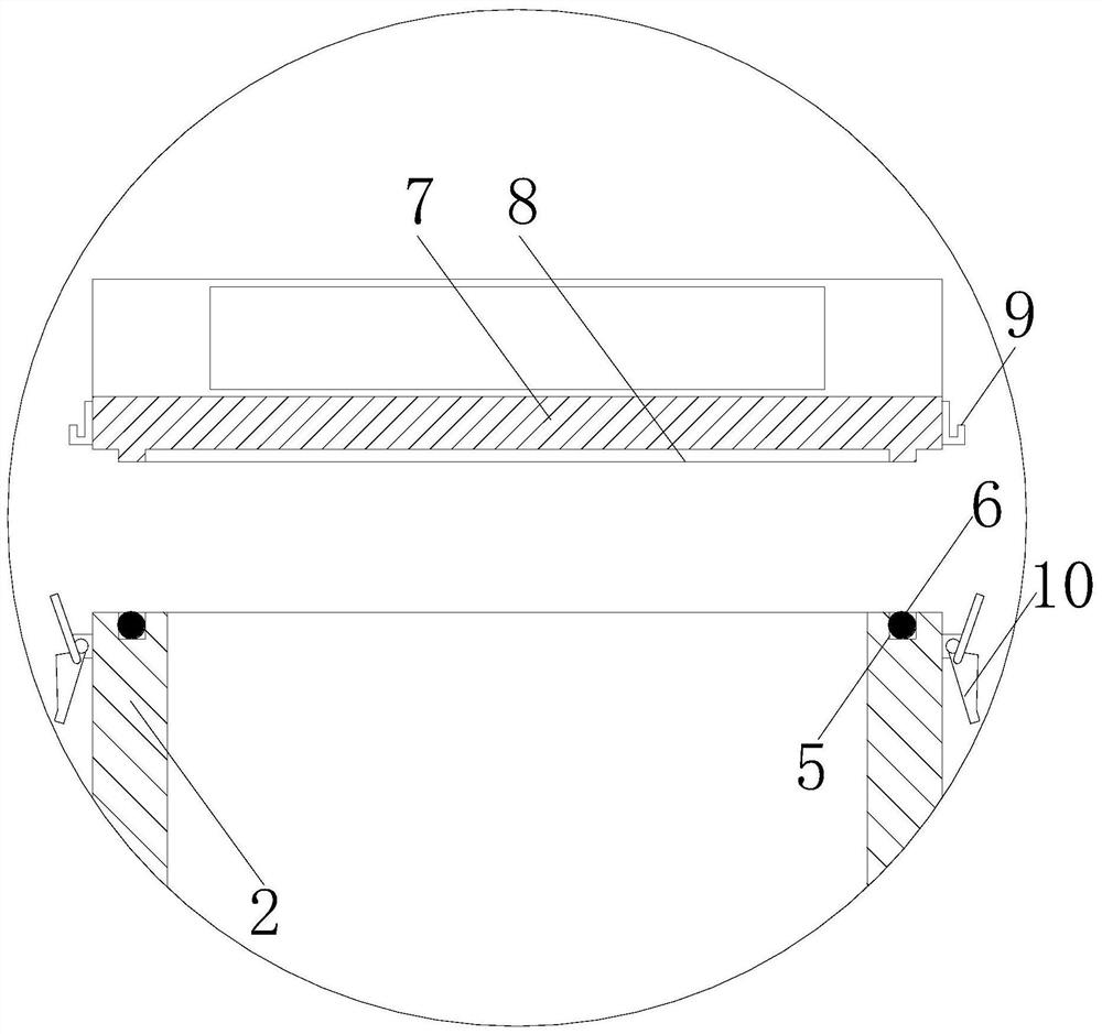
[0048] The intelligent fire extinguisher box with weight monitoring, as shown in the figure, includes an extension plate 1, a box body 2, a rib plate 3, a ground nail 4, an annular groove 5, a sealing ring 6, an end cover 7, an annular convex strip 8, and a hook 9 , a lock 10, a grid 11, a through hole 12, an electronic scale 13, wherein an extension plate 1 is provided at the bottom end of the outer wall of the box body 2, and a rib plate 3 is fixedly connected between the extension plate 1 and the box body 2, and the ground The nail 4 penetrates the epitaxial plate 1 and is anchored to the ground. There is an annular groove 5 at the top of the box body 2, and a sealing ring 6 is built in the annular groove 5. There is an annular convex strip 8 at the lower end of the end cover 7. A hook 9 is fixedly connected to the outer wall, a lock 10 is fixedly connected to the outer wall of the box body 2, the end cover 7 is buckled on the top of the box body 2, the lock 10 is snapped an...

Embodiment 2

[0051] Smart fire extinguisher box with weight monitoring, such as Figure 1~5 As shown, it includes epitaxial plate 1, box body 2, rib plate 3, ground nail 4, annular groove 5, sealing ring 6, end cover 7, annular convex strip 8, hook 9, lock buckle 10, grid frame 11, through hole 12. Electronic scale 13, wherein an extension plate 1 is provided at the bottom end of the outer wall of the box body 2, a rib plate 3 is fixedly connected between the extension plate 1 and the box body 2, and ground nails 4 penetrate the extension plate 1 and are anchored to the ground, There is an annular groove 5 at the top of the box body 2, a sealing ring 6 is built in the annular groove 5, and an annular convex strip 8 is provided at the lower end of the end cover 7, and a hook 9 is fixedly connected to the outer wall of the end cover 7. The outer wall of 2 is fixedly connected with a lock 10, the end cover 7 is buckled on the top of the box body 2, the lock 10 is snapped and fixed with the ho...


PUM


Abstract

The invention discloses an intelligent fire extinguisher cabinet and a working method thereof, which realize more convenient and reliable fire extinguisher maintenance and state monitoring. In the intelligent fire extinguisher cabinet, an extension plate is arranged at the bottom end of the outer wall of a cabinet body, a rib plate is fixedly connected between the extension plate and the cabinet body, a ground nail penetrates through the extension plate and is anchored to the ground, an annular groove is formed in the top end of the cabinet body, a sealing ring is arranged in the annular groove, and an annular convex strip is arranged at the lower end of an end cover; a hook is fixedly connected to the outer wall of the end cover, a lock catch is fixedly connected to the outer wall of the box body, the end cover is buckled at the top end of the box body, the lock catch and the hook are clamped and fixed, the annular convex strip is inserted into the annular groove and abuts against the sealing ring, a net rack is fixedly connected to the inner wall of the box body, and a through hole is formed in the middle part of the net rack; an electronic scale is placed on the inner bottom surface of the box body and located below the net rack; and the bottom of a fire extinguisher extends downwards through the through hole and is arranged on the surface of the electronic scale.

Description

technical field [0001] The invention relates to the technical field of fire fighting equipment, in particular to an intelligent fire extinguisher box with weight monitoring. Background technique [0002] In various key firefighting units, we often need to use fire extinguisher boxes, install a fixed number of fire extinguishers, and place them in conspicuous positions. In addition to the role of the so-called "container", it can also play a role in positioning, preventing loss, and protecting the fire extinguisher from external collisions. In an emergency, the red box is more conspicuous and can be quickly identified effect. [0003] Fire extinguishers need to be inspected regularly, and carbon dioxide fire extinguishers often use the weighing inspection method. Simply put, it is to weigh the carbon dioxide fire extinguisher every six months, and compare the difference between the current weight and the factory weight. If the weight difference of the gas component is great...

Claims


Application Information

Patent Timeline
Patent Type & Authority Applications(China)
IPC IPC(8): A62C37/50G08B7/06G08B17/06G08B17/10G08B25/10G01G19/52H05K5/02H05K5/03H05K5/06
CPCA62C37/50G01G19/52G08B7/06G08B17/06G08B17/10G08B25/10H05K5/0204H05K5/0217H05K5/03H05K5/061
Inventor 卢冠军卢秋锦
Owner 卢冠军
Why Eureka
Try Eureka