A cooling device for a weft feeder

A technology of heat dissipation device and weft feeder, which is applied in textiles, textiles, papermaking, looms, etc., and can solve the problems of inconspicuous heat dissipation, poor heat dissipation, and burnt circuit boards, etc.

Active Publication Date: 2018-04-24
苏州盛泽科技创业园发展有限公司
View PDF5 Cites 0 Cited by
  • Summary
  • Abstract
  • Description
  • Claims
  • Application Information

AI Technical Summary

Problems solved by technology

The drum-type weft feeder uses the yarn storage drum with a large moment of inertia as the rotating part of the yarn winding, which is obviously very unfavorable for high-speed looms
[0005] With the continuous advancement of technology, the electronic weft feeder has entered the textile machinery industry and has become the main component of the current textile machinery. The existing electronic weft feeder is equipped with a circuit board inside to control the working state, but in order to improve the utilization rate, often The weft feeder is in an uninterrupted working state, and the circuit board will continuously generate heat. At present, the heat dissipation device of the circuit board generally adopts the traditional method of adding an aluminum plate on the circuit board as a radiator. Due to the weft storage Due to the limitation of the internal volume of the machine case, the aluminum plate radiator is generally small, so the heat dissipation effect is not good, and the circuit board in a high temperature state for a long time may burn out
Although the installation structure of adding an aluminum plate on the circuit board as a heat sink is simple, the heat dissipation effect is not obvious, and it is easy to damage the power board of the weft feeder, thereby affecting production efficiency

Method used


Image

  • A cooling device for a weft feeder
  • A cooling device for a weft feeder
  • A cooling device for a weft feeder

Examples


Embodiment Construction

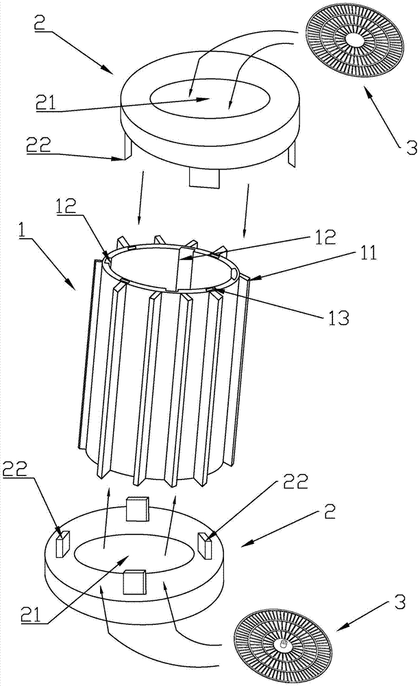
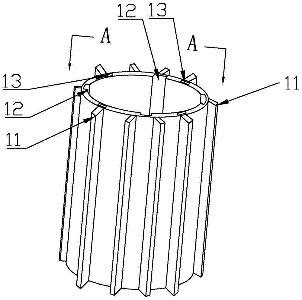
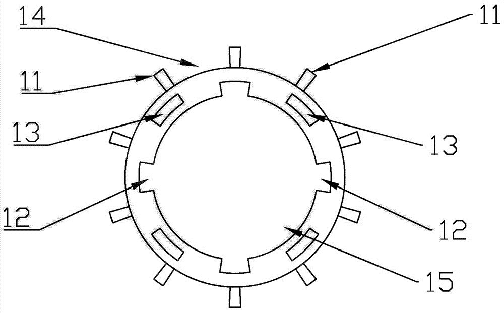
[0039] Such as Figure 1 to Figure 15 As shown, a heat dissipation device for a weft feeder includes a heat dissipation cover 2 and a heat dissipation housing 1. Both ends of the heat dissipation cover 2 are connected to the heat dissipation cover 2, and a heat dissipation disk 3 is installed in the heat dissipation cover 2. Heat dissipation fins 11 are arranged on the outer circumference of the heat dissipation housing 1 . The heat dissipation fins 11 are arranged on the outer circumference of the heat dissipation housing 1 in a circumferential manner, and housing heat dissipation passages 14 are formed between the heat dissipation fins 11 . There are 10 radiating fins 11, and housing radiating passages 14 are formed between them to discharge heat outside the weft feeder. The inner circumference of the heat dissipation housing 1 is provided with a wire routing groove 12 , and a wire routing mechanism is arranged in the wire routing groove 12 . The routing mechanism includes ...


PUM


Abstract

The invention discloses a heat dissipation device for a weft feeder, which comprises a heat dissipation cover and a heat dissipation housing. Both ends of the heat dissipation cover are connected with the heat dissipation cover. Lugs, a wire routing mechanism is provided on the inner circumference of the heat dissipation shell, and a heat dissipation groove is provided in the middle of the heat dissipation cover. The heat dissipation groove matches the heat dissipation disk. The heat dissipation disk includes a central disk body and an outer wheel disk. A first heat dissipation ring and a second heat dissipation ring are provided between them, a first heat dissipation strip is provided between the center plate body and the first heat dissipation ring, a second heat dissipation strip is provided between the first heat dissipation ring and the second heat dissipation ring, and a second heat dissipation strip is provided between the first heat dissipation ring and the second heat dissipation ring. A third heat dissipation strip is arranged between the second heat dissipation ring and the outer disc. The device has the advantages of simple structure, scientific convenience, convenient manufacture, low cost, strong pertinence, good heat dissipation effect, and greatly prolongs the service life of the weft feeder.

Description

technical field [0001] The invention relates to a cooling device for a weft feeder. Background technique [0002] With the continuous development of the textile industry, our country is in the critical period of textile industry upgrading. A large number of emerging textile enterprises rely on technological progress and participate in the current fierce market competition. The focus of competition is the adjustment of product structure, the improvement of product grade and quality , and the fundamental shortcut to solve the problem of upgrading products is to accelerate the pace of technological progress in the weaving industry. [0003] The weft insertion rate of modern shuttleless looms is very high, usually above 1000m / min, the highest has exceeded 2000m / min, and the weft insertion process only takes 1 / 2 to 1 / 3 of the time of one revolution of the main shaft of the loom, so the weft yarn The take-out speed from the bobbin is very high, which is equivalent to 2 to 3 times...

Claims


Application Information

Patent Timeline
Patent Type & Authority Patents(China)
IPC IPC(8): D03D47/34
Inventor 杨春霞
Owner 苏州盛泽科技创业园发展有限公司
Why Eureka
Try Eureka