
Cloth special-purpose sucker and work method thereof

A suction cup and cloth technology, applied in the direction of cloth feeding mechanism, textile and papermaking, sewing equipment, etc., can solve the problems that the suction force is difficult to control, cannot adapt to mechanical automation sewing, and cannot send cloth to other problems, so as to avoid adsorption multi-layer cloth effect

Active Publication Date: 2015-12-23
SHANGHAI WEISHI MACHINERY
View PDF7 Cites 5 Cited by
  • Summary
  • Abstract
  • Description
  • Claims
  • Application Information

AI Technical Summary

Problems solved by technology

[0004] The technical problem to be solved in the present invention is: the existing cloth suction cup may cause the cloth to have a certain displacement in the air, and cannot accurately and quickly send the cloth to the required processing station; or cause the suction to be difficult to control, which is often not the suction If you can't live, you can absorb multiple pieces of fabric at one time, which makes it impossible to adapt to mechanical automation sewing

Method used


Image

  • Cloth special-purpose sucker and work method thereof
  • Cloth special-purpose sucker and work method thereof
  • Cloth special-purpose sucker and work method thereof

Examples


Embodiment Construction

[0025] The present invention will be further described below in conjunction with the accompanying drawings and specific embodiments.

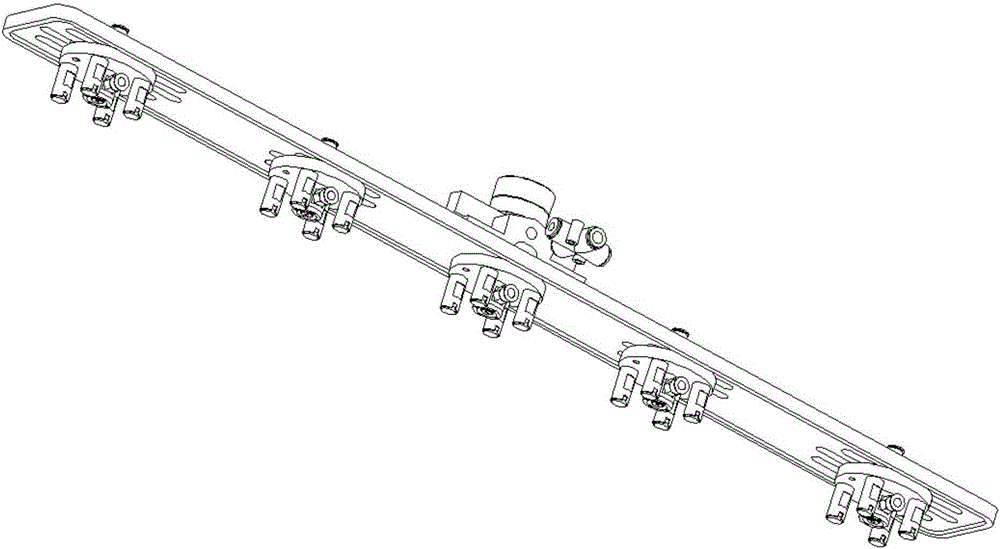
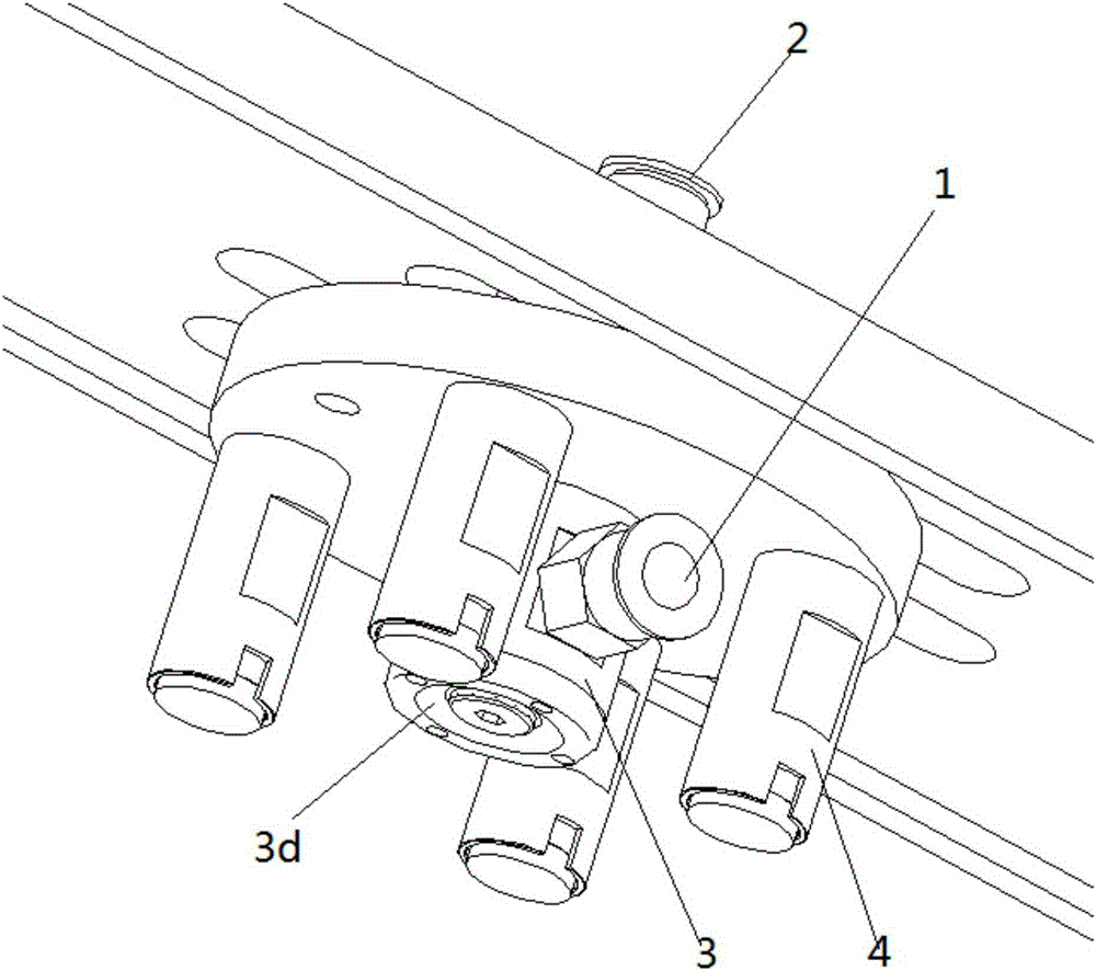
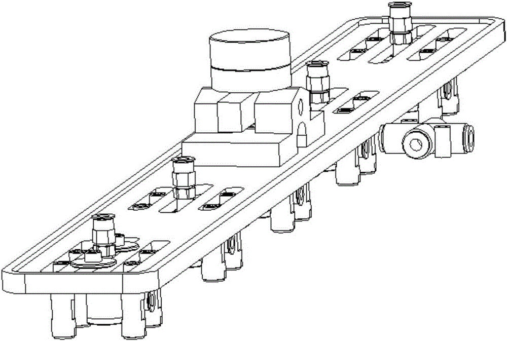
[0026] see Figure 1-Figure 5 , a special suction cup for cloth, including a mobile bracket, a group of suction cup units are fixedly connected to the bottom of the mobile bracket; the suction cup unit includes an air blowing port 1, an air suction port 2, a suction cup core 3, and a cloth pressing support column 4; The suction cup core 3 is a columnar body, the blowing port 3b on its side is connected to the blowing port 1, and the blowing port 1 is connected to the blowing pressure device, and there is a negative pressure generating area 3d below the non-contact suction cup 3c at the bottom of the suction cup core 3 There is a vertical suction channel in the center of the suction cup core 3, the suction port 3a at the top of the suction channel is connected with the suction port 2, and the suction port 2 is communicated with the suction press...


PUM


Abstract

The invention relates to a cloth special-purpose sucker comprising a mobile support; a group of sucker units are fixed below the mobile support, and each unit comprises a blowing end port (1), a sucking end port (2), a sucker core (3) and a cloth press support rods (4); the sucker core (3) is in a cylinder shape; a blowing port (3b) on the side face of the sucker core (3) is connected with the blowing end port (1); the blowing end port (1) is connected with a blowing pressure device; a negative pressure generation zone (3d) is arranged below a non-contact sucker (3c) on the bottom of the sucker core (3); the center of the sucker core (3) is provided with a vertical suction channel; a suction port (3a) on the top of the suction channel is connected with the sucking end port (2); the sucking end port (2) is connected with a suction pressure device; the bottom of the suction channel is a vacuum sucker; the non-contact sucker (3c) carries out non-contact suction on the cloth, then the mobile support rises to lift up the single layer cloth, the vacuum sucker firmly sucks the cloth, and the cloth can be transversely transferred.

Description

technical field [0001] The invention relates to a special suction cup for cloth, belonging to the technical field of cloth suction cups for automatic sewing machine garment processing. Background technique [0002] Cloth suction cups are used in the field of automatic sewing machines to absorb and transfer a single layer of cloth horizontally or vertically. [0003] The existing cloth suction cups have two forms: vacuum adsorption type and non-contact suspension adsorption type. The non-contact suction cup can suck the cloth to a suspended state, but when the cloth is suspended and adsorbed, the shape of the cloth is often unstable, and the cloth will inevitably produce certain damage in the air. Therefore, the cloth cannot be accurately and quickly sent to the required processing station; the vacuum suction cup is directly vacuumed, and the suction force is difficult to control. For some light and thin cloth, it is often either unable to absorb or disposable Many pieces of...

Claims


Application Information

Patent Timeline
IPC IPC(8): D05B35/00
Inventor 柴国宣李振宝
Owner SHANGHAI WEISHI MACHINERY
Learn More