Setting-up construction method for vertical joint bars of columns in reverse building method

A technology of construction method and reverse method, applied in artificial islands, water conservancy projects, infrastructure engineering and other directions, can solve the problem of reducing the area of ​​soil excavation at the column head, unfavorable foundation pit enclosure and soil deformation control outside the pit, unfavorable problems. Accurate positioning, etc.

Active Publication Date: 2015-12-23
SHANGHAI NO 4 CONSTR
View PDF8 Cites 3 Cited by
  • Summary
  • Abstract
  • Description
  • Claims
  • Application Information

AI Technical Summary

Problems solved by technology

[0004] In the existing upside-down method of column head construction, all the soil at a certain depth below the column head is excavated, which is not conducive to the deformation control of the foundation pit enclosure and the soil outside the pit; moreover, the vertical reinforcement passes through the bottom form of the column head formwork The rear suspension is unfavorable for its accurate positioning. The purpose of the present invention is to provide a construction method for vertically inserting bars in the column in the reverse method. The annular groove is made by partially excavating the soil around the steel column, so that The vertical reinforcement of the column can pass through the bottom formwork of the beam-column formwork and be inserted into the space of the annular groove and fixed, thereby reducing the excavation area of ​​the soil at the column head and reducing the adverse effect on the foundation pit structure, and The end of the vertical reinforcement is buried in the compacted packing layer, which has the function of accurately positioning the vertical reinforcement

Method used


Image

  • Setting-up construction method for vertical joint bars of columns in reverse building method
  • Setting-up construction method for vertical joint bars of columns in reverse building method
  • Setting-up construction method for vertical joint bars of columns in reverse building method

Examples


Embodiment Construction

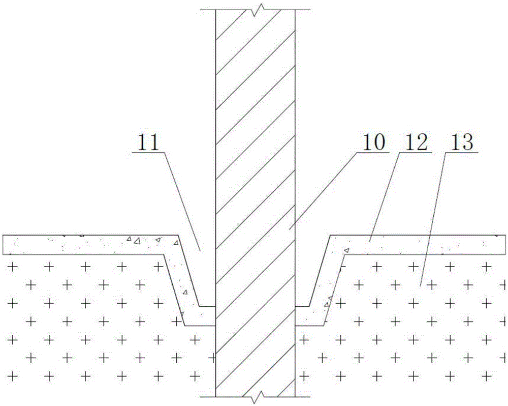
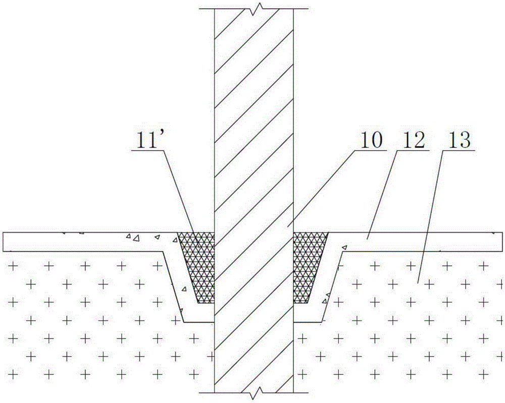
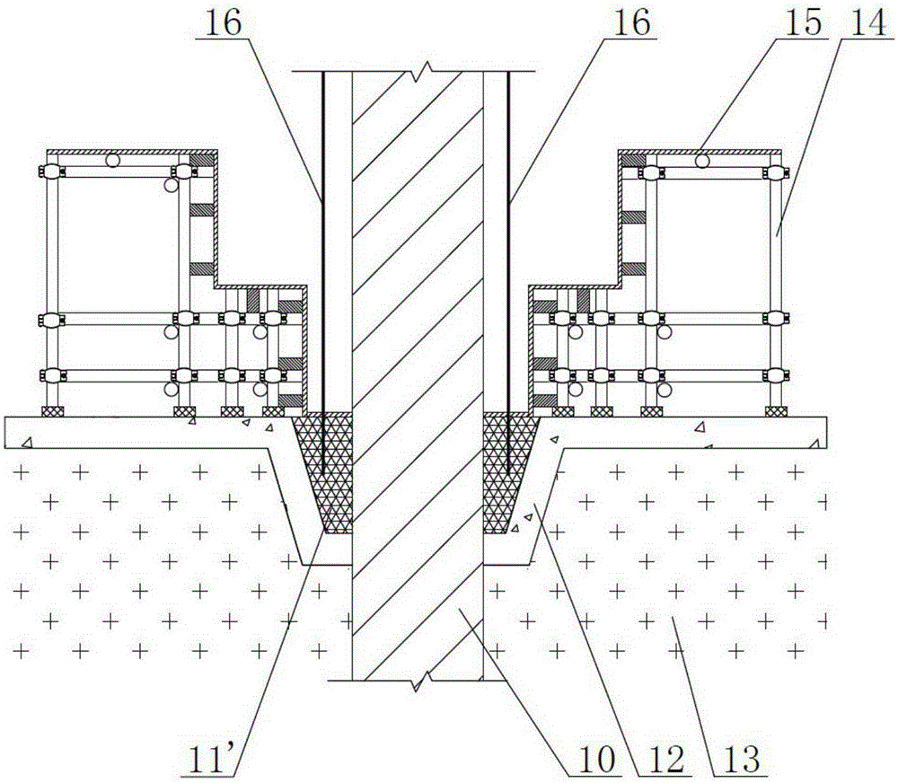
[0020] In the following, a working method for retaining the vertical reinforcement of columns in a reverse method proposed by the present invention will be further described in detail in conjunction with the accompanying drawings and specific embodiments. Advantages and features of the present invention will be apparent from the following description and claims. The technical content and features of the present invention will be described in detail below by referring to the illustrated embodiments in conjunction with the accompanying drawings. It should be further noted that all the drawings are in very simplified form and use imprecise scales, and are only used to facilitate and clearly assist the purpose of illustrating the embodiments of the present invention. For the convenience of description, the "up" and "down" described below are consistent with the directions of up and down in the drawings, but this should not be a limitation of the technical solution of the present i...


PUM


Abstract

The invention relates to the technical field of building construction, in particular to a setting-up construction method for vertical joint bars of columns in a reverse building method. The problems that in column end construction of an existing reverse building method, soil below column ends by a certain depth is all excavated to be unfavorable to deformation control over foundation pit supports and soil outside pits, and due to the fact that vertical joint bars are suspended after penetrating bottom molds of column end form boards, the vertical joint bars cannot be accurately located are solved. The method comprises the following steps that firstly, soil is locally excavated deeply along a steel column to manufacture an annular groove, and a plain concrete cushion layer is poured; secondly, the annular groove is backfilled with packing, and a packing layer is obtained through punning; thirdly, bent frames and beam column form boards are erected on the plain concrete cushion layer, bottom molds of the beam column form boards are laid on the packing layer, beam column steel bars and the vertical joint bars are arranged, and the bottom ends of the vertical joint bars penetrate the bottom molds of the beam column form boards and are inserted in the packing layer downwards; and fourthly, concrete is poured in the beam column form boards, after the strength of the concrete meets the design requirement, the bent frames and the beam column form boards are demounted, and the plain concrete cushion layer and the packing layer are excavated together during lower-layer soil excavation.

Description

technical field [0001] The invention relates to the technical field of building construction, in particular to a construction method for vertically inserting ribs of columns in the upside-down method. Background technique [0002] As we all know, upside-down construction is an environmentally friendly construction technology that uses horizontal floors instead of supports. It can not only greatly save project cost and shorten the construction period, but also effectively reduce the lateral deformation of the foundation pit enclosure and improve the stability of the foundation pit. Safety is a deep foundation pit support technology with great development prospects and popularization value. However, the problem that needs to be solved during the construction is that when the next step of earthwork excavation is carried out after the construction of the horizontal structure of this road, the horizontal structure that has been constructed is in a suspended state. For the load t...

Claims


Application Information

Patent Timeline
Patent Type & Authority Applications(China)
IPC IPC(8): E02D29/05
Inventor 孔德志张铭朱海峰陈建江石勇陈梦然陈磊
Owner SHANGHAI NO 4 CONSTR
Why Eureka
Try Eureka