Method for controlling bridge deformation in engineering of underneath passing high-speed railway bridge on road

A bridge engineering and road technology, which is applied in the field of bridge deformation control, can solve problems such as difficult to meet the strict displacement restrictions of the pier abutment top, reduce the difficulty and construction operation risk, reduce the difficulty and time, and control the deformation value Effect

Pending Publication Date: 2021-07-09
CHINA RAILWAY LIUYUAN GRP CO LTD
View PDF6 Cites 2 Cited by
  • Summary
  • Abstract
  • Description
  • Claims
  • Application Information

AI Technical Summary

Problems solved by technology

[0004] In order to solve the above-mentioned technical problems, the present invention provides a method for controlling the deformation of the bridge in the bridge engineering of the high-speed railway passing under the road, which overcomes the difficulty of existing solutions in meeting the strict displacement restrictions of the pier abutment top in the new regulations, and can control the deformation of the bridge pier The deformation of the abutment top meets the requirements of the new regulations, that is, under the condition of the high-speed railway with no speed limit for the underpass project, the lateral, longitudinal and vertical displacement limits of the abutment top are 3mm and 2mm for the ballasted track and the ballastless track respectively

Method used


Image

  • Method for controlling bridge deformation in engineering of underneath passing high-speed railway bridge on road
  • Method for controlling bridge deformation in engineering of underneath passing high-speed railway bridge on road
  • Method for controlling bridge deformation in engineering of underneath passing high-speed railway bridge on road

Examples


Embodiment Construction

[0031] In order to enable those skilled in the art to better understand the technical solution of the present invention, the present invention will be described in detail below in conjunction with the accompanying drawings and specific embodiments.

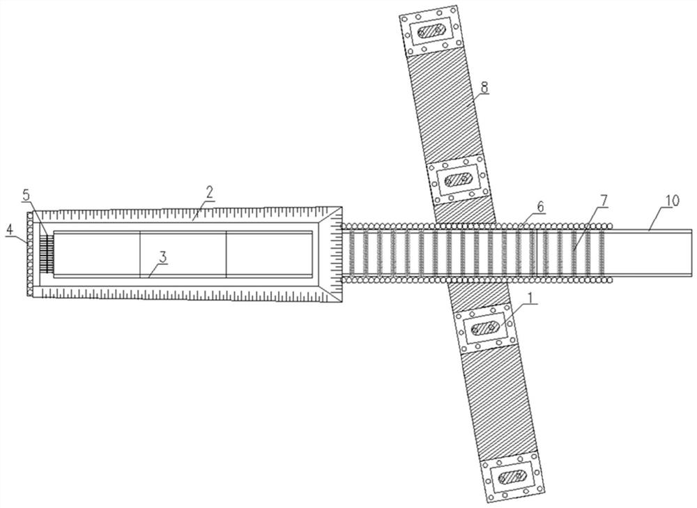
[0032] This embodiment provides a method for controlling the deformation of the bridge in the high-speed rail bridge project under the road, such as Figure 1 to Figure 4 As shown, the method includes the following steps:

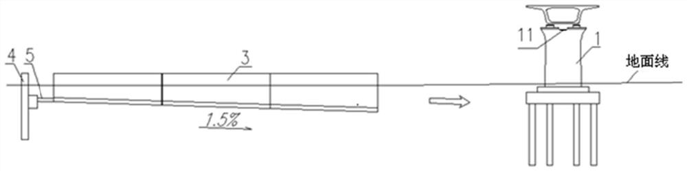
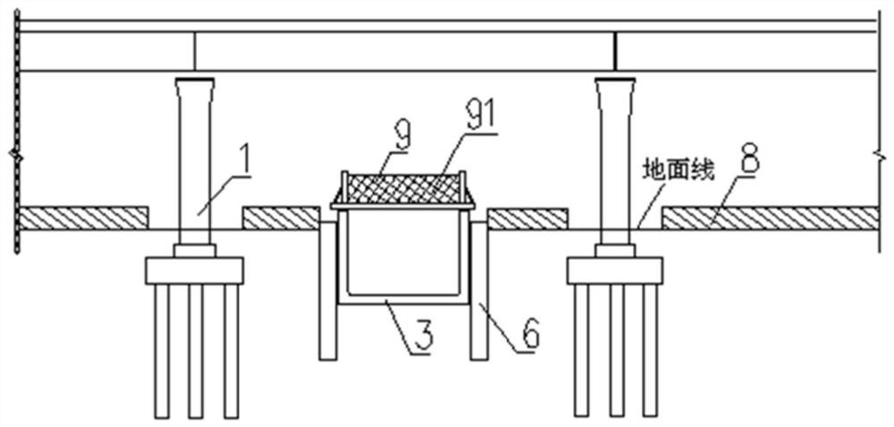
[0033] Step S1, taking the deformation of the pier top as the control condition to calculate the lengths of the U-shaped groove 3 of the lower jacking section and the U-shaped groove 10 of the cast-in-place section of the existing high-speed rail bridge 1 . According to the depth and size of the prefabricated foundation pit 2 of the U-shaped groove 3 in the jacking section, calculate and determine the distance between the foundation pit 2 and the existing high-speed rail bridge 1 and the underground road protec...


PUM


Abstract

The invention provides a method for controlling bridge deformation in a road underneath pass high-speed rail bridge project. The method comprises the steps: calculating the lengths of U-shaped grooves in a lower jacking section and a cast-in-place section of an existing high-speed rail bridge, the distance between a foundation pit and the existing high-speed rail bridge and the number and length of underground road protection piles on the two sides of the U-shaped grooves in the underneath pass range of the existing high-speed rail bridge; excavating a foundation pit in a layered mode, prefabricating a jacking section U-shaped groove structure, arranging a temporary U-shaped groove jacking rigid frame on the jacking section U-shaped groove structure, constructing a back pile, and installing a jack jacking system; while the foundation pit is excavated, constructing road protection piles; solidifying soil under a bottom plate of the U-shaped groove structure of the jacking section; gradually jacking the jacking section U-shaped groove in the direction of the existing high-speed railway bridge along the designed gradient, and excavating a soil body at the front end of the jacking section U-shaped groove while jacking is conducted; in the jacking process, dynamically controlling the ballasting measures; after the U-shaped groove of the jacking section is in place, constructing the U-shaped groove of the cast-in-place section; and gradually reducing the weight. The bridge pier abutment top deformation can be controlled to meet the new regulation requirement.

Description

technical field [0001] The invention belongs to the technical field of bridge engineering, and in particular relates to a method for controlling bridge deformation in a bridge engineering under which a road crosses a high-speed rail. Background technique [0002] With the rapid development of China's high-speed railways, there are more and more cases where new roads pass under existing high-speed railway bridges. The "Technical Regulations for Underpassing High-speed Railways in Highway and Municipal Engineering" (TB 10182-2017) was implemented on April 1, 2018. The regulations stipulate that: under the condition of no speed limit for high-speed railways, the horizontal, vertical and The vertical displacement limit is 3mm and 2mm for ballasted track and ballastless track respectively. Before the implementation of the new regulations, the routine excavation of the ground before the construction of subgrades, cast-in-place pile-slab structures or cast-in-place U-shaped groove...

Claims


Application Information

Patent Timeline
Patent Type & Authority Applications(China)
IPC IPC(8): E01D19/02E01D21/00E01B29/16
CPCE01D19/02E01D21/00E01B29/16
Inventor 尤广杰曹全王鲁王彦李黎周津斌赵彦峰刘向琼高荣辉
Owner CHINA RAILWAY LIUYUAN GRP CO LTD
Why Eureka
Try Eureka