
Expanding mechanical air suction control device

A technology of a control device and an expansion cylinder, applied in the field of expansion machinery

Active Publication Date: 2015-12-23
ZHUHAI GREE REFRIGERATION TECH CENT OF ENERGY SAVING & ENVIRONMENTAL PROTECTION
View PDF7 Cites 15 Cited by
  • Summary
  • Abstract
  • Description
  • Claims
  • Application Information

AI Technical Summary

Problems solved by technology

[0006] The present invention aims to provide an expansion machine suction control device to solve the serious problem of the axial transmission of the crankshaft in the existing expansion machine

Method used


Image

  • Expanding mechanical air suction control device
  • Expanding mechanical air suction control device
  • Expanding mechanical air suction control device

Examples


Embodiment Construction

[0024] The embodiments of the present invention will be described in detail below with reference to the accompanying drawings, but the present invention can be implemented in many different ways defined and covered by the claims.

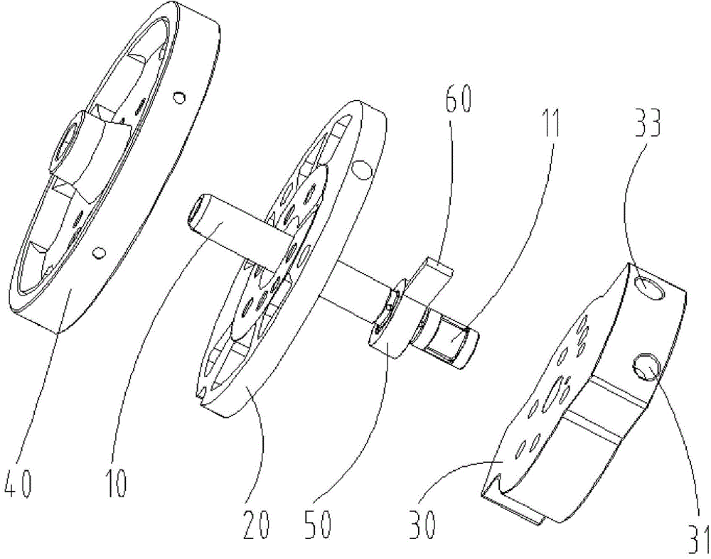
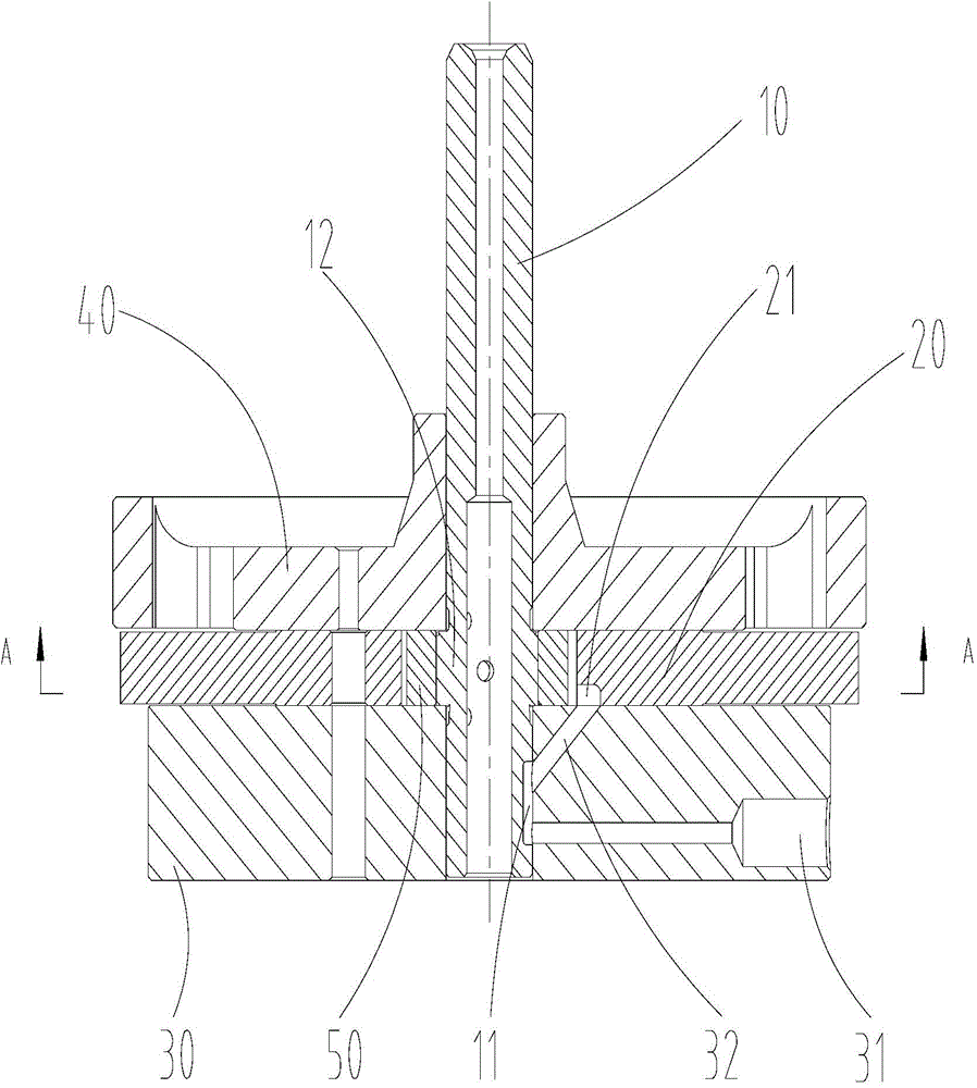
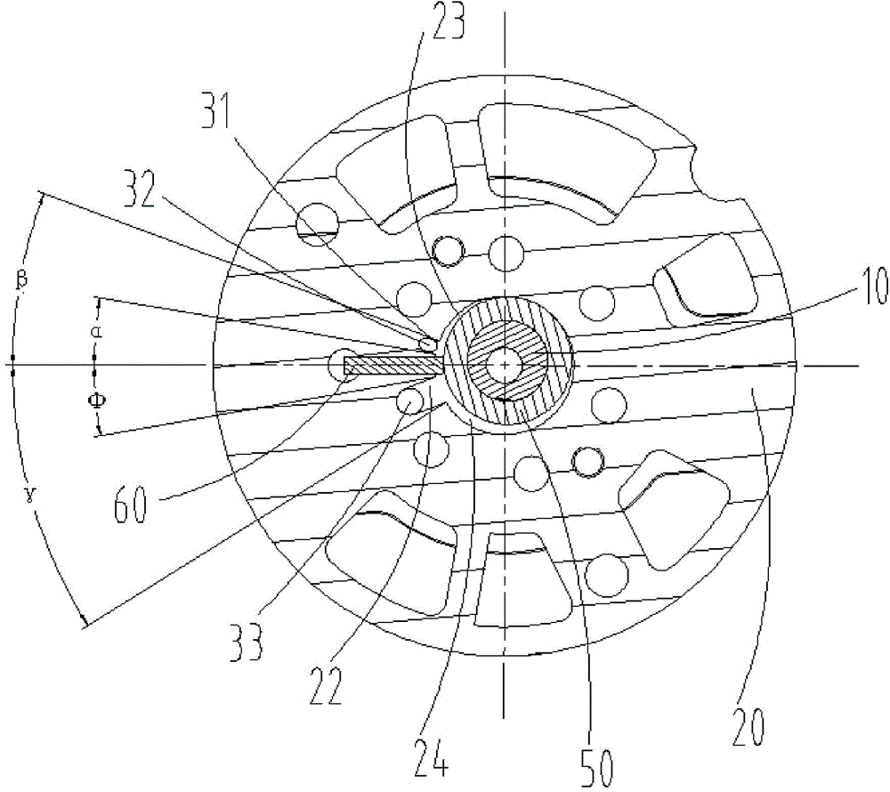
[0025] combine Figure 1 to Figure 5 As shown, according to the embodiment of the present invention, an expansion mechanical suction control device is provided. The expansion mechanical suction control device includes a crankshaft 10 , an expansion cylinder 20 , a first flange 30 and a second flange 40 . Among them, the expansion cylinder 20 is sleeved on the crankshaft 10; the first flange 30 is sleeved on the crankshaft 10 and is located on the first side of the expansion cylinder 20; the second flange 40 is sleeved on the crankshaft 10 and is located on the expansion cylinder 20 on the second side. In order to reduce and prevent the crankshaft 10 from moving in the axial direction, the arrangement of the high-pressure fluid channel of the expan...


PUM

PropertyMeasurementUnit
Angleaaaaaaaaaa

Abstract

The invention provides an expanding mechanical air suction control device. The expanding mechanical air suction control device comprises a crankshaft, an expanding air cylinder, a first flange and a second flange, wherein the expanding air cylinder sleeves the crankshaft, the first flange sleeves the crankshaft and is arranged on the first side of the expanding air cylinder, and the second flange sleeves the crankshaft and is arranged on the second side of the expanding air cylinder. The first flange is provided with a first high-pressure fluid channel which extends from the outer edge of the first flange to the crankshaft, and the first flange is also provided with a second high-pressure fluid channel communicated with an air cylinder inlet of the expanding air cylinder; the crankshaft is provided with a first groove, and the first groove is provided with a conveying portion for communicating the first high-pressure fluid channel and the second high-pressure fluid channel. The expanding mechanical air suction control device can effectively reduce and avoid axial movement of the crankshaft and enhance the stability of the expanding air cylinder and the crankshaft in the process of operation.

Description

technical field [0001] The present invention relates to the technical field of expansion machinery, and more particularly, relates to an air suction control device for expansion machinery. Background technique [0002] Patent No. 201180001766.6 discloses a fluid machine and refrigeration cycle device, including an expander with an expander suction hole and an expander discharge hole. The suction hole of the expander and the suction hole of the compressor are closed with the rotation of the shaft; when the suction hole of the compressor is closed, the suction hole of the expander is open, and when the suction hole of the expander is closed, the suction hole of the compressor is open And do not communicate with the compressor discharge hole. This structure has the following problems: [0003] (1) The suction hole of the expander is at the bottom of the lower bearing. After the high-pressure fluid is introduced into the bottom, there is an upward impact on the fan-shaped cam ...

Claims


Application Information

Patent Timeline
IPC IPC(8): F01C1/356F01C21/18
Inventor 梁志礼胡余生徐嘉任丽萍杜忠诚吕林波孔令超
Owner ZHUHAI GREE REFRIGERATION TECH CENT OF ENERGY SAVING & ENVIRONMENTAL PROTECTION
Learn More